ISSN ONLINE(2319-8753)PRINT(2347-6710)
ISSN ONLINE(2319-8753)PRINT(2347-6710)
| P.Saravanan and R.Elavarasi Department of EEE, Valliammai Engineering College, Anna University, Chennai, India |
| Related article at Pubmed, Scholar Google |
Visit for more related articles at International Journal of Innovative Research in Science, Engineering and Technology
This paper presents an efficient methodology for integration of Distributed Generation (DG) power into distribution systems, in order to maximize the voltage limit loadability. The proposed methodology is based on continuation power flow (CPF). The effectiveness of the presented methodology is demonstrated in a test distribution system that consists of 85 nodes with integration of different penetration levels of DG power. The proposed method yields efficiency in obtaining more benefits from the same amount of DG power, decreasing the losses and improving the voltage profile. The simulation of the proposed model was carried out using MATLAB/PSAT and the effective performance was analyzed.
Index Terms |
| Distributed generation, Distributed network, Continuation Power Flow (CPF) method, Voltage stability, Voltage limits. |
INTRODUCTION |
| In general terms, voltage stability is defined as the ability of a power system to maintain steady voltages at all the buses in the system after being subjected to a disturbance from a given initial operating condition. It depends on the ability to maintain equilibrium between load demand and load supply from the power system. Instability that may result appears in the form of a progressive fall or rise of voltages of some buses. Voltage stability problems mainly occur when the system is heavily stressed beyond its capability. While the disturbance leading to voltage collapse may be initiated by a variety of causes, the main problem is the inherent weakness in the power system. |
| Recently a top priority is given to develop a reliable, sustainable, environment friendly as well as low-cost electrical energy supply. This includes a sensible energy mix and improvements in efficiency of energy generation, transmission and consumption[1]. As a number of events that have been brought to the vulnerability of the current centralized electrical energy supply infrastructure, such as terrorist threats, natural disasters, geopolitical disruptions, ageing of a highly complex infrastructure, climate change and regulatory and economic risks, DG appears to be one of the key answers for different problems[3]. In the distribution system, the electrical power supply will be transferred from a vertical one to a horizontal system. In the traditional systemthe electric power industry has been driven by a paradigm where most of the electricity is generated in large power plants, sent to the consumption areas through HV transmission lines, and delivered to the consumers through a passive distribution infrastructure that involves HV, MV and LV networks. In this paradigm power flows only in one direction from the power station to the network and to the consumer. |
| The DG term is used to describe small distribution system close to the point of consumption. Such generators may be owned by a utility or more likely by a customer who may use the entire portion or perhaps all of it to the local utility combustion turbine generators, internal combustion engines and generators, photovoltaic panels, and fuel cells. Solar thermal conversion, stirling engines, are considered as DG. When the penetration of DG is high, the generated power of DG units not power flow in the distribution network consequence, the connection of DG to the grid may different technical issues, e.g. voltage profiles quality, stability etc..[8] In spite of the benefits of utilizing DG units within of the system efficiency and the improvements in the technical and operational challenge units into MV distribution networks are needed. Moreover, in more details with respect to the generation types. Optimization of the MV distribution networks with a large penetration of DG is also needed therefore the utilities can get more benefits[9]. |
| Many voltage stability indices are based on the eigen value analysis or singular value decomposition of the system power flow Jacobian matrix. The main difficulty in this method is that Jacobian of NR power flow become singular at voltage stability limit (critical point) .A power flow solution near the critical point prone to divergences and error. Singularity in the Jacobian can be avoided by slightly reformulating the power flow equations and applying a locally parameterized continuation technique. During the resulting continuation power flow, the reformulated set of equations remains well conditioned so that divergence and error due to a singular Jacobian are not encountered. |
CONTINUATION POWER FLOW |
| The continuation method is a mathematical pathfollowing methodology used to solve systems of nonlinear equations. Using the continuation method, a solution branch can be tracked around the turning point without difficulty. This makes the continuation method quite attractive in approximations of the critical point in a power system. The CPF captures this pathfollowing feature by means of a predictor-corrector scheme [11]. Moreover, CPF can be used to determine generator reactive |
 |
 |
 |
 |
PLACEMENT ALGORITHM |
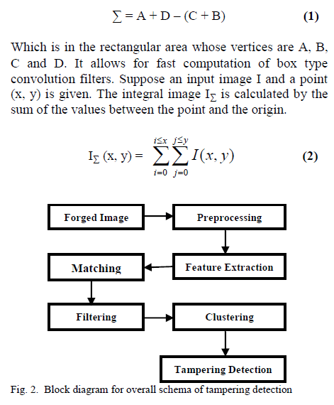
| Different recommended locations for integration of DG forincreasing the amount of loads which can be supplied from the system through enhancing the VLL of the system are the main objective of the suggested methodology. The proposed algorithm is depicted in Fig. 2. The methodology starts with execution of CPF to specify the VLL of the base case of the system and identify the first node which reached the low voltage limit. Then the DG unit with a certain power is integrated at that node and after that the CPF is executed. Therefore, another node can be obtained and then the DG units’ power is dispersed between the resulted nodes according to their loads, then the VLL is checked. This process is continued until no improvement is obtained and as a result the methodology will be ended. Different steps of the proposed algorithm are summarized as follows: |
| Step 1: Identifying the first node reached the low voltage limit in the network using CPF. |
| Step 2: Integrating the DG units at that node and examine the VLL of the network. |
| Step 3: Running the CPF with DG. |
| Step 4: Identifying another node which reached the low voltage limit using CPF. |
| Step 5:Dispersing the DG power between the recommended nodes according to their loads. |
| Step 6: Running the CPF with DG. |
| Step 7: Examining the VLL with the existence of the different number of DG units. |
| Step 8: Go to step 4 if an improvement in VLL is achieved otherwise go to step 9. |
| Step 9: End. |
 |
SIMULATION STUDY |
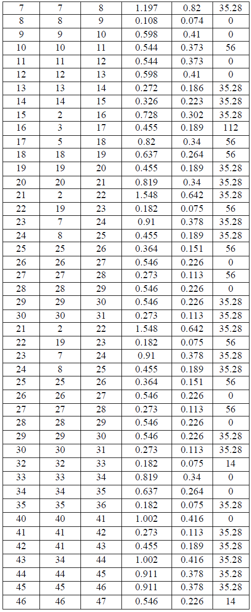
| The placement methodology is implemented on an 85 node radial distribution network[8](seeFig. 2). The data of thesystem is giveninTable. I. The system was built into PSAT and as a first step the CPF is executed where the limitwas identified to be the low voltage limit. That means theloading parameter (λ) will be increased at all nodes with the same value till the voltage at one node reaches the minimum voltage limit. The VLL can be specified based onthe value of k which has been found in this step to be 1.1515 which means that the load at each node can be increased to be 115.2% of its base case whiles the voltage at all nodes are within the limits. Node no. 54 was found to be the first node reached the low voltage limit. According to the methodology all the DG units (6 X240 kW) are integrated at this node. With integration of the DG units at node no. 54 the CPF is executed for the second time till the voltage at another node reaches the low minimum value.The loading factor (λ) in this step was found to be 1.8229, which means that the VLL is 3.3 MW[15]. Moreover, it has |
 |
| Been found that node no. 76 is the node which reaches the minimum voltage limit.Then according to the procedure of the algorithm the DG power were dispersed between nodes No. 54 and 76. That means at each node three DG units were integrated.Then, with the existence of the DG units at nodes No. 54, and 76 the CPF is executed for the third time. In this case the VLL is improved to be 3.68MW with a maximum loading factor of 2.0419. Through this step node No. 47 was the node which first reached the low voltage limit. Therefore, the six DG units were dispersed at the three nodes 54, 76, and 47 with two DG units at each node. The network with presence of the DG units at the three nodes is tested with CPF and in this step the VLL was 3.8MW with a maximum loading factor of 2.1093. |
| The loading factor (k) in this step was found to be 1.8229, which means that the VLL is 3.3 MW. |
 |
| Then according to the procedure of the algorithm the DG power were dispersed between nodes No. 54 and 76. (Fig.4)That means at each node three DG units were integrated. Then, with the existence of the DG units at nodes No. 54, and 76 the CPF is executed for the third time. In this case the VLL is improved to be 3.68MW with a maximum loading factor of 2.0419. Through this step node No. 47 was the node which first reached the low voltage limit. |
 |
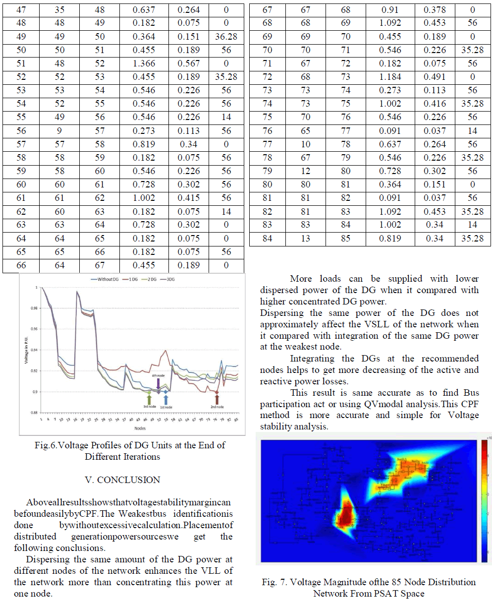
| Moreover, it has been found that node no. 76 is the node which reaches the minimum voltage limit [13] (see fig 3). Therefore, the six DG units were dispersed at the three nodes 54, 76, and 47 with two DG units at each node.The network with presence of the DG units at the three nodes is tested with CPF and in this step the VLL was 3.8MW with a maximum loading factor of 2.1093.The improvement in percentage is calculated relative to the base case. It can be demonstrated that VLL is improved when the DG power is dispersed between the resulted nodes (Fig.5). A 515 kW is the difference in VLL of the system between integrating two units at each node of the three resulted nodes and integrating the six units at one node. This means that the network can be loaded by 15.7% more than the case of concentrated DG units at node No. 54 (Fig.6) while the voltages are kept within the limits. |
 |
 |
 |
ACKNOWLEDGMENT |
| The authors would like to thank the editor and anonymous reviewers whose comments and suggestions have improved the quality of this paper. |
References |
|