ISSN ONLINE(2319-8753)PRINT(2347-6710)
ISSN ONLINE(2319-8753)PRINT(2347-6710)
Anumolu Lasmika 1, K. Raveendra 2
|
| Related article at Pubmed, Scholar Google |
Visit for more related articles at International Journal of Innovative Research in Science, Engineering and Technology
In research and investigations satellite images become more popularity to getting data to accomplish their needs. While getting this data some disturbances are getting along with this that is nothing but poor image quality. To overcome this we present DWT to decompose the input image into different sub bands with powerful theoretical tool to analyse the nonlinear image. Identifying the areas of the edges through threshold decomposition and edges are sharpened by using morphological filters. By this we are improving the better quality of image.
Keywords |
| Discrete wavelet transforms (DWT), Threshold decomposition, Morphological filter, Satellite image enhancement. |
I. INTRODUCTION |
| Nowadays satellite images are being used in several applications such as meteorology, agriculture, geology, forestry, landscape, biodiversity conservation, regional planning, education, intelligence and warfare. Satellite images are affected by various factors such as absorption, scattering etc in the space. So the resolution of these images is very low. To acquire better perception of these images, it is necessary to have the image with clear and well defined edges, which provides better visible line of separation etc. |
| Enhancing the resolution of an image is most important in the field of image processing. Enhancing the resolution of an image includes improving the number of pixels available to represent the details of image. A common Resolution Enhancement (RE) technique is to vary the size of dots like pixels. Image resolution means the detail an image holds. Higher resolution means that more image detail. Image enhancement is one of the preprocessing techniques. The preprocessing is used to condition the image before going for processing. |
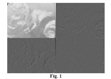
| Resolution enhancement of these images has always been a major issue to extract more information from them. There are many approaches that can be used to enhance the resolution of a satellite image. Wavelet domain based methods have proved themselves as most efficient technique serving for the required purpose. Resolution has been frequently referred as an important aspect of an image. Images are being processed in order to obtain more enhanced resolution. Resolution enhancement is classified into several types such as pixel resolution, spatial resolution, spectral resolution, temporal resolution etc. In DWT each decomposition divides an image into four quadrants. Two-dimensional frequency partition produces four sub bands: LL, LH, HL and HH. |
 |
| The figure 1 shows four sub bands of input image. One of the commonly used techniques for image resolution enhancement is Interpolation. Interpolation has been widely used in several image processing applications such as multiple description coding, facial reconstruction, and super resolution. There are three well known interpolation techniques, namely nearest neighbor interpolation, bilinear interpolation, and bucolic interpolation. Image resolution enhancement in the wavelet domain is a relatively new research topic and recently many new algorithms have been proposed. |
II. OVERVIEW OF RESOLUTION ENHANCEMENT TECHNIQUES |
| A. Wavelet Zero Padding: |
| In previous wavelet zero padding is one of the simplest methods or image resolution enhancement. It assumes that the signal is zero outside the original support. The most common form of zero padding is to append a string of zero-valued samples to the end of sometime-domain sequence. Zero padding is used in spectral analysis with transforms to improve the accuracy of the reported amplitudes, not to increase frequency resolution. Without zero-padding, input frequencies will be attenuated in the output. Zero padding in the time domain is equivalent to optimal interpolation in the frequency domain, which restores the correct amplitudes. Since the wavelet transform is defined for infinite length signals, finite length signals are extended before they can be transformed. One of the common extension methods is zero padding. Zero padding shifts the inter sample spacing in frequency of the array that represents the result. In image resolution enhancement, wavelet transform of a low resolution (LR) image is taken and zero matrices are embedded into the transformed image, by discarding high frequency sub bands through the inverse wavelet transform and thus high resolution (HR) image is obtained. |
| In this method, wavelet transform of a LR image is taken and zero matrices are embedded into the transformed image, by discarding high frequency sub bands through the inverse wavelet transform and thus HR image is obtained. [2]. |
 |
| B. Cycle Spinning: |
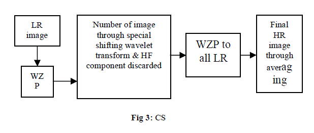
| In Cycle Spinning [2] method, we follow the following steps to get highly resolved image. First we obtain an intermediate HR image through WZP method. After that we obtain N number of images through spatial shifting, wavelet transforming and discarding the high frequency component. Again, the WZP process is applied to all LR images to obtain a number of HR images. These HR images are realigned and averaged to give a final HR image. |
 |
III. PROPOSED ENHANCED METHOD |
| As it was mentioned before, Image enhancement is an important feature in satellite imaging, which makes the image enhancement of such images to be of vital importance as increasing the enhancement of these images will directly affect the performance of the system using these images as input. The edge enhancement filtering is carried out with the help of traditional filters. But these filters do have some problems, especially while enhancing a noisy image. |
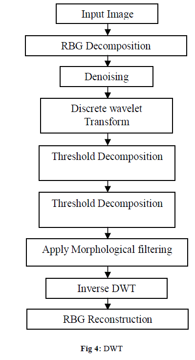
| The effort on edge enhancement has been focused mostly on improving the visual perception of images that are unclear because of blur. Noise removal and preservation of useful information are important aspects of image enhancement. A wide variety of methods have been proposed to solve the edge preserving and noise removal problem. In order to increase the quality of the enhanced image, preserving the edges is essential. Mathematical morphology is the name given to a geometrical branch of nonlinear filters. It offers a unified and powerful approach to numerous image processing problems. One of the most appealing aspects of morphological image processing lies in addressing the image sharpening problem. In this paper, a new edge detected morphological filter is proposed to sharpen aerial images. The low contrast satellite input color images are Fig 3. (a, b, and c) . DWT separates the input image into different sub band images, namely LL, LH, HL, and HH. DWT has been employed in order to preserve the high frequency components of the image. |
 |
| The input low contrast color image is decomposed into R, G; B. DWT is apply to each color(R, G, B) separately. The LL sub band of each color component of the image is decomposing into a series of binary levels, each of which may be processed separately. These binary levels can then be recombined to produce the final gray scale image with identical pixel values to those produced by gray scale processing. The success of threshold decomposition, gradientbased operators is used to detect the locations of the edges, by detecting the positions of the edges and then applying a class of morphological filtering. A morphological filter is used to sharpen these detected edges. Peak signal to noise ratio (PSNR) and root mean square error (RMSE) have been implemented in order to obtain quantitative results. PSNR can be obtained by using the following formula: |
 |
| Where R is the maximum fluctuation in the input image (255 is here as the images are represented by 8 bit ;) MSE is representing input image I1 and proposed enhanced imageI2 which can be obtained by the following formula: |
 |
| The general procedure of the proposed technique is shown in Fig(2) as follows |
| The result images can be evaluated with two characteristics, distortion and sharpness. According to the distortion evaluation, adjusting errors are required, by computing the Mean Square Error (MSE). Peak Signal to Noise Ratio (PSNR) adjusts the quality of the image which the higher the PSNR refers to the better quality is the image. |
IV. RESULT AND DISCUSSION |
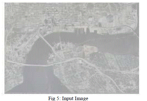
| The results for the enhancement of satellite images are given. The images tested in the proposed method were performed shown in figure d, e and f which were express in the numerical form of satellite image. The result image can be evaluated with two characteristics, distortion and sharpness. According to the distortion evaluation, adjusting errors are required, by computing the Mean Square Error (MSE). Mean square error has been the performance metric in lost performance. Peak Signal to Noise Ratio (PSNR) adjusts the quality of the image which the higher the PSNR refers to the better quality is the image. The input images and proposed enhanced images MSE and PSNR are tabulated in Table.1. PSNR (db) quantity is high in proposed image enhancement techniques Fig.5 and 7 are original images Fig 6 and 8 are enhanced Images using Satellite image enhancement using DWT and threshold decomposition driven morphological filter. The proposed method gives better qualitative and quantitative results .as shown |
 |
 |
| Here the input image is either colour or gray scale which is taken from the satellite. The figure 5 and figure 7 are satellite images with noise, poor illumination which are processed in many stages like discrete wavelet transformation, threshold decomposition and morphological filtering and finally the enhanced images figure 6 and figure 8 are obtained. |
CONCLUSION |
| In our proposed method in enhancing low contrast satellite images, edge detected guided smoothing filters turn out well. The precision maintained in detecting the positions of the edges through threshold decomposition, where the sharpening of the detected edges was done by applying smoothing filter, over the consumption of the detected edges, our scheme was capable to efficiently sharpening into fine details. The proposed method was ominously better than many other well-known sharpener-type filters in respect of edge and fine detail restoration, have confirmed in the shown visual examples where The PSNR improvement of the proposed technique is elevated. |
References |
|