Keywords
|
| multilevel inverters, permanent magnets, diode-clamped, flying capacitor, cascaded, induction motor |
I. INTRODUCTION
|
| With advancement of static switch devices technology such as IGBTs with voltage rating up to 4.5 kV commercially available, has made the use of the voltage source inverters (VSI) feasible for high power applications. High power and high-voltage conversion systems have become very important issues for the power electronic industry handling the large ac drive and electrical power applications at both the transmission and distribution levels. High power ratings is not possible for a two-level inverter, as the semiconductor devices must be connected in series to obtain the required high-voltage operation, this can be achieved by summing the outputs of several two-level converters with transformers or inductors, or direct series connection, or by some topologies such as the diode clamped inverter and the flying capacitor inverter which are usually termed as multilevel voltage source inverters. |
| The multilevel voltage source inverters unique structure allows them to reach high voltages with low harmonics without the use of transformers or series-connected synchronized switching devices, for high-voltage, high power applications. The general structure of the multilevel converter, which has a multiple of the usual six switches found in a three-phase inverter, is to synthesize a sinusoidal voltage from several levels of voltages, typically obtained from capacitor voltage sources. The main motivation for such converters is that current is shared among these multiple switches, allowing a higher converter power rating than the individual switch VA rating would otherwise allow with low harmonics. As the number of levels increases, the synthesized output waveform, a staircase like wave, approaches a desired waveform with decreasing harmonic distortion, approaching zero as the number of levels increases. |
| There are three main types of transformer less multilevel inverter topologies, which have been received considerable interest from high-power inverter systems are the flying-capacitor inverter, the diode-clamped inverter, and the cascaded H-bridge inverter. In this paper we choose to work on cascaded H-bridge inverter due to its advantages: |
| 1. It uses fewer components than the other types. |
| 2. It has a simple control, since the converters present the same structure. |
| 3. Soft-switching technique can be used to reduce switching losses and devices stresses. |
| Because of these advantages, the cascaded inverter bridge has been widely applied to such areas as HVDC, SVC, stabilizers, and high-power motor drives. |
II. MODELLING OF BLDC MOTOR
|
| The modelling is carried based on assumptions that |
| i) Uniform air gap |
| ii) Balanced rotor and stator windings with sinusoidally distributed mmf Modelling is done in two axis model i.e., in d-q axis. Three phase supply is transformed into two phase by parks transformation and the corresponding stator voltage equations is developed in stator reference framewich are as below |
 |
| Where Rs - Rotor resistance |
| Ls – Self inductance of each phase windings |
| Lm – Mutual inductance |
| iqs, ids, iqr,idr – Currents in stator windings |
| Θr – rotor position |
| From state space model currents are derived from above equations. Using the obtained currents the electromagnetic torque is given by |
 |
| Where wm – rotor speed in mechanical rad/s |
| B – friction coefficient |
| J – Inertia of motor shaft |
III.SIMULATION OF CASCADED H-BRIDGE MLI
|
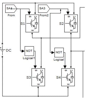
| Simulation of MLI is carried out by using MATLAB. Cascaded MLI consists of series H Bridges, each H-Bridge consists of series H- Bridges, each Bridge consists of four switches as shown in fig.1 |
| The output generated by each H-Bridge is of three different levels i.e, +Vdc, 0, -Vdc by connecting dc source to the ac output side by different combinations of the four switches, S1,S2,S3,S4. Turning on S1, S4 gives +Vdc. Turning on S2,S3 yields –Vdc. Turning off all switches gives 0V. In the same manner output at each level is obtained. The switching sequence for a single bridge is as follows, the firing pulse for upper switches S1,S3 has phase delay of 1800 . The lower switches are compliments firing pulse given through NOT gate. The same holds good for any no of bridges connected either in single phase or three phase. Here three phase cascaded MLI is simulated. For N-level output no of bridges required per phase is given by N=2n+1. |
| Where n= no of bridges |
| For 5 level we require 2 bridges per phase. |
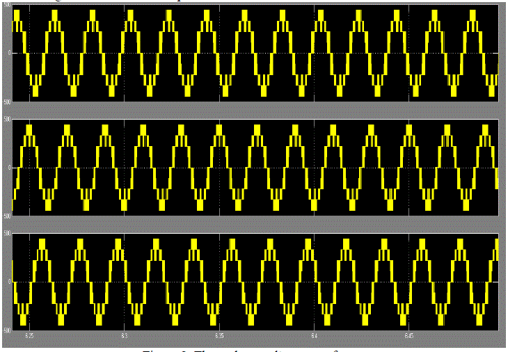
| Controlling the conducting angles at different inverter levels can minimise the harmonic distortion of the output voltage. As the no of levels increases the output voltage tends to sinusoidal. |
A. Switching Technique
|
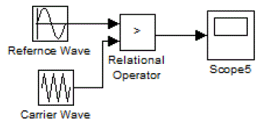
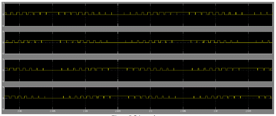
| Switching is implemented by sinusoidal pulse width modulation. In pulse width modulation the firing pulses required for semiconductor switches is obtained by comparing reference wave with carrier wave. In sinusoidal pulse width modulation technique sinusoidal wave is taken reference wave and triangular wave as carrier wave. The output of inverter i.e. amplitude and frequency can be varied by changing the reference wave amplitude and carrier wave frequency respectively. Amplitude modulation index is ratio of reference wave amplitude to carrier wave amplitude ma = Vr / Vc. The frequency modulation is defined as ratio of carrier wave frequency to reference wave frequency mf = fc /fr. In this paper the amplitude modulation is taken as ma = 1 and the frequency modulation mf =21. The pulses are generated as below in figure |
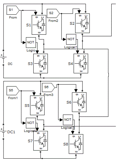
| Here the MLI is three phase the firing pulses are given with phase delay of 1200 to each leg. The switches in a single leg are connected as shown in fig.4 |
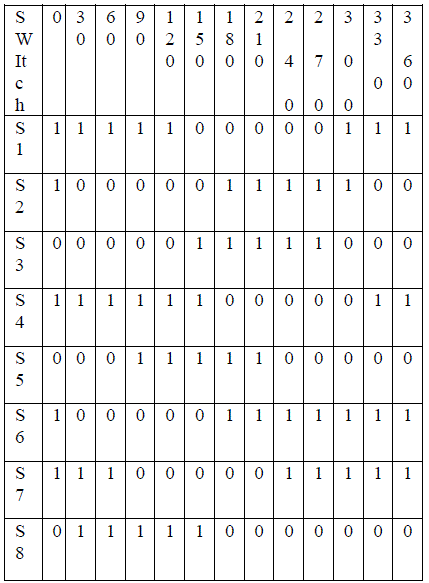
| The switch S1 and S2 has phase delay of 1800. Switch S1 and S5 has phase delay of 900. Switches S3,S4 are compliment for switch S1, S2 respectively and similarly S7,S8 are compliment to switch S5,S6. In the same the other two legs are connected and switching is done in the similar fashion. |
| The switching pattern is tabulated below is for one leg of three phase inverter |
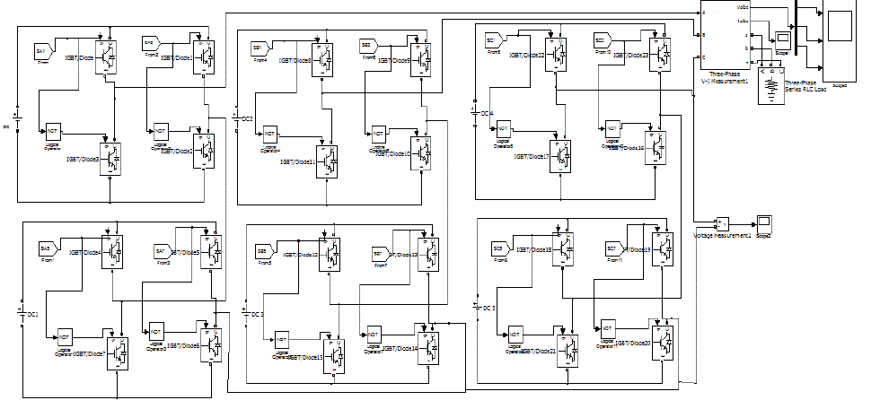
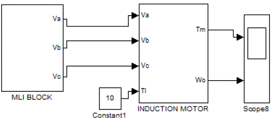
| The overall Simulink model is as below |
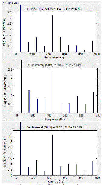
iii. FFT Analysis of Output Phase Voltages
|
| Total harmonic distortion of three phase voltages are as shown |
V.CONCLUSION
|
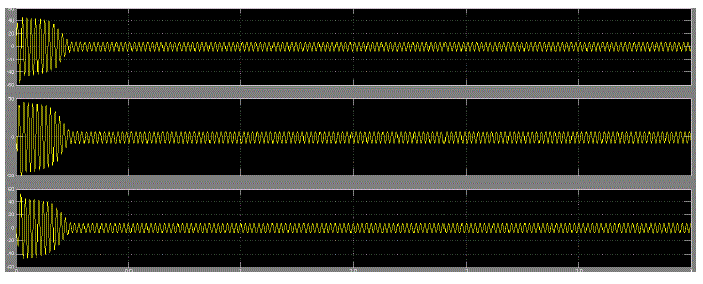
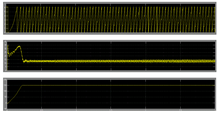
| In this paper simulation of five level cascaded mli is done using MATLAB. The three phase voltages are fed to MATLAB model of induction motor. The simulation results shows the performance characteristics of induction motor, the stator currents and electromagnetic torque magnitudes are also obtained in the graphs. The rotor position found out at every instant and is as shown in the graph. |
| |
Figures at a glance
|
 |
 |
 |
 |
 |
| Figure 1 |
Figure 2 |
Figure 3 |
Figure 4 |
Figure 5 |
 |
 |
 |
 |
 |
| Figure 6 |
Figure 7 |
Figure 8 |
Figure 9 |
Figure 10 |
 |
| Figure 11 |
|
| |
References
|
- R. Krishnan, “Electric Motor Drives Modelling, Analysis and Control”, Prentice Hall, 2001.
- M.Rashid “Power electronics Handbook”, AcademicPress.
- John Wiley & Sons, Parker, R.J., “Advances in Permanent Magnetism”, 1990.
- NedMohan, Undeland, Riobbins “Power electronic converter, applications and design” ,Wiley Student Edition.
- R. Krishnan, “Permanent Magnet Synchronous and Brushless DC Motor Drives”, CRC Press, 2010.
|