Keywords
|
| PMSM, Direct torque control, MTPA, Input Output feedback linearization. |
INTRODUCTION
|
| Permanent Magnet Synchronous Motors (PMSM) are attracting growing attention for a wide variety of industrial applications, from simple applications like pumps, fans to high performance drives. This is due to their main characteristics like high power density, high torque to inertia ratio and high efficiency. Nowadays, DTC [1] is considered as the most important technique applied to AC motors for achieving high dynamic performance.The main disadvantages of DTC are- difficult to control flux and torque at low speed, current and torque distortion during the sector change, variable switching frequency, need of high sampling frequency in case of digital implementation of hysteresis controllers, high torque ripple. For overcoming these problems, although several methods are proposed in the literature, the most popular method is DTC-SVM method. This paper deals with a robust DTC-SVM method for flux & torque control of a PMSM drive based on Input Output Feedback Linearization technique. |
PMSM MODELLING
|
| According to the theory of AC motors, the mathematical model of the PMSM is developedaccording to the generalized theory of machines as follows: |
Stator Voltage equations
|
 (1) (1) |
 (2) (2) |
Stator Flux Linkages
|
 (3) (3) |
 (4) (4) |
| d& q axis currents |
 (5) (5) |
 (6) (6) |
| where Rs is the stator resistance, r ïÃÂ÷ is the electrical rotor speed, Vd&Vq are d and q axis voltages respectively. Similarly id&iqare d and q axis currents andLq&Ld are q and d axis inductances respectively. f ïÃÂù is the flux linkage between magnetic field of the permanent magnet and the stator windings |
| The equation for electromagnetic torque for a PMSM is given by; |
 (7) (7) |
| The vector transformation equations for the Park’s Transformation, which is utilized in this work, are given below. |
 (8) (8) |
 (9) (9) |
DTC- SVM BASED CONTROL OF PMSM
|
| Principle behind direct torque control (DTC) is the direct selection of voltage vectors according to the error between reference & actual value of torque and flux linkage. These errors are controlled with a hysteresis comparator in classical DTC. According to the output of hysteresis comparator, a voltage vector is selected from a table.Although it has many advantages like low complexity, no need of rotor position sensor etc.,there should be the disadvantage of relatively high ripple level in torque, flux linkage and stator current and also it has a variable switching frequency.Many methods have been proposed in the literature for overcoming these disadvantages [2-4]. The most popular method used to reduce the torque ripple is to incorporate space vector modulation(SVM)with DTC [5]. In DTC-SVM method, hysteresis comparators are replaced by an estimator .This estimator will calculates the appropriate voltage vectors which will compensates the torque & flux error. |
| By providing the reference values for torque & flux according to the operating conditions, a DTC system can achieve high performance and optimal control. Here a reference calculator is provided for calculating the reference value for flux & torque[6]. These values are compared with the actual values of torque & flux. The error is controlled with a Torque & Flux controller. Flux reference is calculated with the use of Maximum Torque Per Ampere (MTPA) principle [7].The merit of using MTPA is the minimization of electrical losses and hence maximum drive efficiency. |
INPUT OUTPUT FEEDBACK LINEARIZATION BASED CONTROL
|
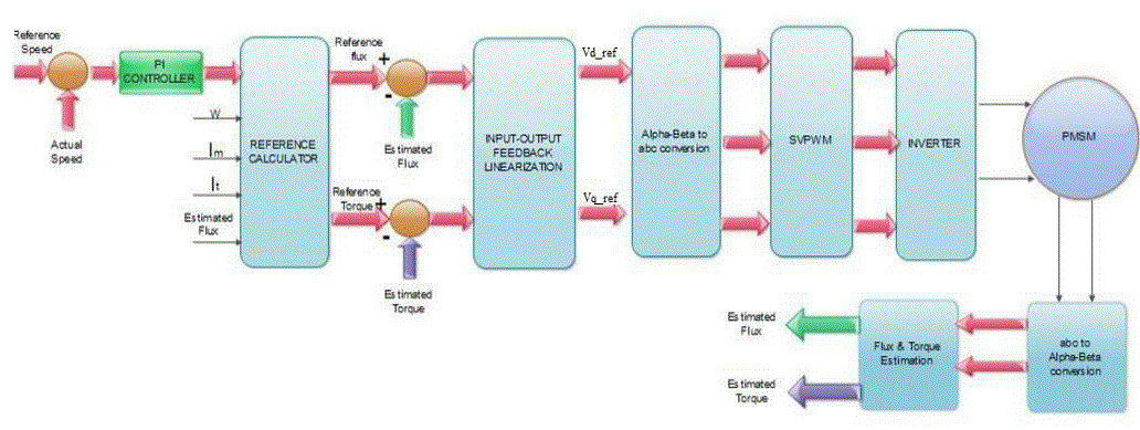
| Feedback Linearization algebraically transforms a nonlinear system dynamics into a linear one, so that linear control techniques can be applied. 2 types of feedback linearization are – Input Output & Input State feedback linearization. Out of which Input- Output feedback linearization method is applied here [8]. The block diagram of DTC-SVM with IOFL technique is given below. |
| For the proposed controller, state coordinate transformation is required. The state coordinate transformed model of PMSM can be rewritten as, (From Equations 3,4,5,6) |
 (10) (10) |
 (11) (11) |
Where,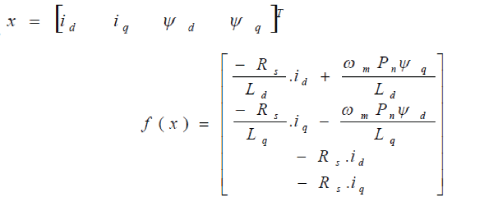 |
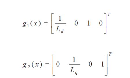 |
| In DTC,we directly controls the Torque & Flux. So in this paper, torque and squared modulus of the stator flux linkages are taken as the output of the system.ie, |
 (12) (12) |
 (13) (13) |
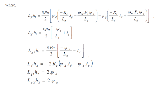
| Then we will apply Input Output feedback linearization method .For linearizing the nonlinear model of Eqn(8), differentiate the variables to be controlled ( Torque & Flux )with respect to time until the input appears so that we will get a linear relationship between input & output. This can be easily done with the help of Lie Derivatives. |
 (14) (14) |
 (15) (15) |
| Where, |
 |
Non-Linear Control law
|
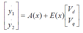
| The relation between the input and derivative of output can be written as; |
 |
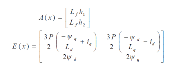 |
| From the above Eqn:, we can calculate the reference value of voltage vectors as follows, |
 (17) (17) |
| Here V1,V2are the inputs ie, Torque & Flux.For getting a better tracking towards their reference values and for ensuring a perfect regulation, V1,V2are selected as follows, |
 (18) (18) |
 (19) (19) |
| K1 and K2 are constant parameters designed to make the decoupled system stable. |
SIMULATION RESULTS
|
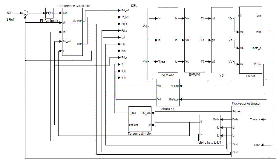
| The effectiveness of the proposed method of Torque & Flux control of PMSM is verified by simulation studies, which are done with the help of MATLAB/SIMULINK environment. |
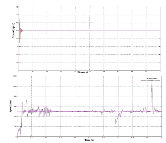
| A. Speed Response |
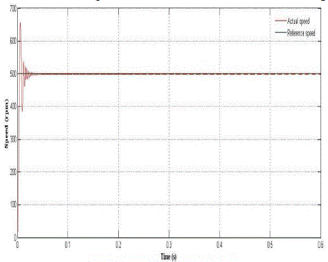
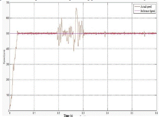
| For the same reference speed of 500 rpm, the performance of the proposed method & DTC-SVM method is compared. From the resulting waveforms, we can observe that the proposed technique has low speed ripple & better tracking. |
| B. Torque Response |
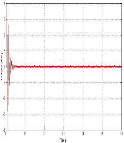
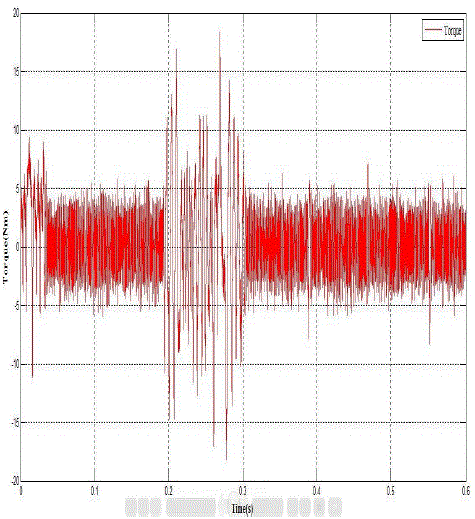
| The motor torque of the proposed method is compared with that of DTC-SVM method. Results clearly projects that the Proposed method has a very low torque ripple compared to that of DTC-SVM method.By using the proposed method, we can reduce the amount of torque ripple. Load Torque is taken as zero. |
| C. Reference Voltage Vector Generation |
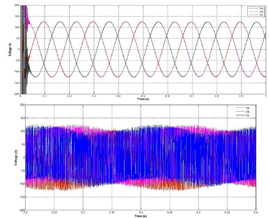
| Using Input Output Feedback Linearization, Reference voltage vectors are calculated in the proposed method.The Reference voltage vectors are more similar to sinusoidal waveform in this method. Hence switching pulses generated by SVPWM are more accurate which in turns leads to the more better driving of the inverter. |
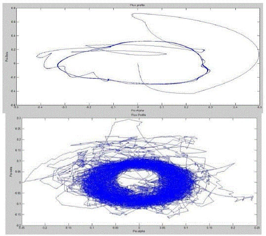
| D. Flux Profile |
| Flux profile of any rotating machine is an indication of speed & torque responses. Since the proposed method gives better flux profile which will makes speed & torque responses much better. |
| E. Variation in the Stator Resistance |
| This section investigates the influence of stator resistance variation in the controller performance. For this,Stator resistance is increased to its 50% .Results prove that stator resistance variation is not affects the proposed controller performance. Hence the proposed IOFL method is more robust against stator resistance variation than DTC – SVM method. |
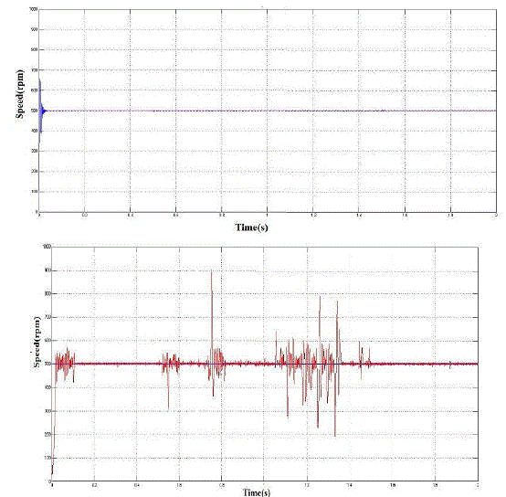
| F. Load Torque Variation |
| The figure given below shows the speed response of DTC –SVM & that of DTC-IOFL under sudden change in Load torque. |
| IOFL based DTC reacts faster than SVM based DTC when load torque is suddenly applied and removed. |
CONCLUSION
|
| In this paper, a robust direct torque control methodfor PMSM drive is proposed. The method incorporates space vector PWM with a torque & flux controller which is realized by input output feedback linearization method. Compared with the ordinary PMSM drives, the proposed technique can be said to have superior characteristics. The overall drive system performance is found to be robust against parameter variations such as stator resistance variation, sudden change in load torque etc. Simulation studies were used to demonstrate the characteristics of the proposed method. It is clear that the proposed controller based on IOFL technique has better tracking performance, reduction in torque ripple and robustness against parameter variations as compared with the DTC-SVM method. |
ACKNOWLEDGMENT
|
| I express my sincere gratitude towards Prof. Mary George, Head of the Department of Electrical Engineering, for her valuable suggestions and support.I express my gratitude to P.G Coordinator, Prof.C.K Vijayakumariand my guide Mrs.Sreelekha V, for their co-operation and guidance for preparing and presenting this paper. I would like to thank them for being patient with me and for helping me to understand the shortcomings in my work.Last but not the least; I acknowledge the grace and power of Almighty God without whose blessings none of this would have been possible. |
Figures at a glance
|
 |
 |
 |
 |
 |
| Figure 1 |
Figure 2 |
Figure 3 |
Figure 4 |
Figure 5 |
 |
 |
 |
 |
 |
| Figure 6 |
Figure 7 |
Figure 8 |
Figure 9 |
Figure 10 |
|
References
|
- I.Takahashi and T.Noguchi”A new quick response and high efficiency control strategy for induction motors”,IEEE Trans. Ind. Appl., vol .IA-22, no.5,pp.820-827,Sep./Oct. 1986
- M. Romero, J.H. Braslavsky, M.I. Vall ”Ripple Reduction in Direct Torque and Flux Control of Induction Motors via Sliding Modes”, LatinAmerican Applied Research, Vol. 37,No. 4, Oct. 2007, pp. 289 – 297.
- S. Belkacem, F. Naceri, R. Abdessemed “A Novel Robust Adaptive Control Algorithm andApplication to DTC-SVM of AC Drives” , SerbianJournal of Electrical Engineering, Vol. 7, No. 1, May 2010, pp. 21 – 40
- 4. L. Tang, L. Zhong, M. F. Rahman, and Y. Hu, “A novel direct torque control for interior permanent-magnet synchronous machine drive withlow ripple in torque and flux—A speed-sensorless approach,” IEEE Trans. Ind. Appl., vol. 39, no. 6, pp. 1748–1756, Nov./Dec. 2003.
- T. Habetler, F. Profumo, M. Pastorelli, and L. Tolbert, "Direct torque control of induction machines using space vector modulation,"IEEETrans. Ind. Appl., vol. 28, no. 5, pp. 1045-1053, Sep./Oct. 1992.
- Yukinori Inoue, Shigeo Morimoto and Masayuki Sanada “Control Method Suitable for Direct-Torque-Control-Based Motor Drive SystemSatisfying Voltage and Current Limitations” IEEE Transactions On Industry Applications, Vol. 48, No. 3, May/June 2012
- Ragi R Menon, S. Jebarani Evangeline, AnishGopinath “Modified Direct Torque Control of Permanent Magnet Synchronous Motor by usingvoltage vectors of variable amplitude and angle “IJEAT, ISSN: 2249 – 8958, vol.2, Dec 2012.
- M. Hajian, J. Soltani, G.R.A. Markadeh, S. Hosseinnia “Input-output Feedback LinearizationofSensorless IM Drives with Stator and RotorResistances Estimation”, Journal of Power Electronics, Vol. 9, No. 4, 2009, pp. 654 – 666.
|