Keywords
|
| Direct Torque Control (DTC), Induction Motor, Multilevel Inverters, |
INTRODUCTION
|
| The multilevel voltage source inverter is recently applied in many industrial applications such as ac power supplies, static VAR compensators, drive systems, etc. One of the significant advantages of multilevel configuration is the harmonic reduction in the output waveform without increasing switching frequency or decreasing the inverter power output [1]. The output voltage waveform of a multilevel inverter is composed of the number of levels of voltages, typically obtained from capacitor voltage sources, so-called multilevel starts from three levels. The traditional inverters are Voltage Source Inverter (VSI) and Current source Inverter (CSI), which consist of diode rectifier front end, DC link and Inverter Bridge. In order to improve power factor, either an AC inductor or DC inductor is normally used. The DC link voltage is roughly equal to 1.35 times the line voltage and the Voltage source inverter is a buck converter that can only produce an AC voltage limited by the dc link voltage. Because of this nature, the Voltage source inverter based PWM VSI and CSI are characterized by relatively low efficiency because of switching losses and considerable Electromagnetic Interference (EMI) generation. |
| As the number of levels reach infinity, the output THD approaches zero. The number of the achievable voltage levels, however, is limited by voltage unbalance problems voltage clamping requirement, circuit layout, and packaging constraints. The multilevel converter is a promising power electronics topology for high power motor drive applications because of its low electromagnetic interference (EMI) and high efficiency [1-4]. These inverters can solve the problems associated with traditional 2-level inverters. Their topologies, including diode-clamped, flying capacitor , and cascaded H-bridge structures, are intensively studied for high-power applications [1]. Higher output quality can be obtained with fewer cascaded cells and control complexity , and output filters can be remarkably shrunk or even eliminated [6].The induction motor (IM), thanks to its well-known advantages of simple construction, reliability, ruggedness, and low cost, has found very wide industrial applications. Furthermore, in contrast to the commutation dc motor, it can be used in an aggressive or volatile environment since there are no problems with spark and corrosion. These advantages, however, are superseded by control problems when using an IM in industrial drives with high performance demands. |
| Since its introduction, direct torque control (DTC) has become a powerful control scheme for the control of induction motor (IM) drives. The standard DTC scheme uses hysteresis comparators for the control of both stator flux magnitude and electromagnetic torque. This control structure ideally keeps both controlled parameters within the hysteresis bands and results in a non constant switching frequency. One of the methods that have been used by one major manufacturer in multilevel inverters is direct torque control (DTC), which is recognized today as a high performance control strategy for ac drives. Several authors have addressed the problem of improving the behaviour of DTC ac motors, particularly by reducing the torque ripple. However, when the DTC scheme is used in a discrete implementation, both torque and flux exceed the bands imposed by the hysteresis comparators, due to the fixed sampling frequency. |
| By discarding the idea of employing flux and torque sensors to detect the controlled variables, the latter ones are estimated from the terminal motor currents and voltages by means of the IM voltage model. Whereas the stator currents are directly transduced, the stator voltages are obtained by transducing the inverter dc-link voltage and by manipulating its magnitude according to the states of the inverter switches. Direct torque control (DTC) has emerged to become a possible alternative to the well-known vector control strategies for induction motor control systems [3], [4]. Although considerable research has been made into the two-level topologies associated with this method of control, the amount of research carried out to date into DTC systems employing multilevel topologies is still rather limited. The major advantage of the three-level VSI topology when applied to DTC is the increase in the number of voltage vectors available. |
| This means the number of possibilities in the vector selection process is greatly increased and leads to a more accurate control system, which can result in a reduction of the torque and flux ripples. This is of course achieved at the expense of an increase in the complexity of the vector selection process. Although several authors have recently proposed the implementation of DTC utilizing this higher-level topology, their approaches are based on the use of more complex vector selection tables combined with modulation techniques based on analytical methods which have machine parameter dependency [5], [6]. A different approach is a selection table based on the concept of virtual vectors [7]. These new methods considerably increase the complexity of the control strategy when compared to the classical DTC system [3], and they cannot be extended to different multilevel topologies with a higher number of levels because of the table selection method adopted. |
CASCADED H-BRIDGES STRUCTURE AND OPERATION
|
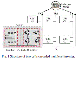
| The traditional two or three levels inverter does not completely eliminate the unwanted harmonics in the output waveform. Therefore, using the multilevel inverter as an alternative to traditional PWM inverters is investigated. The N-level cascaded H-bridge, multilevel inverter comprises series connected single phase H-bridges per phase, for which each H-bridge has its own isolated dc source. |
| Fig. 1 shows a three-phase topology of a cascade inverter with isolated dc-voltage sources. An output phase voltage waveform is obtained by summing the bridges output voltages. The cascaded H-bridge inverter consists of power conversion cells, each supplied by an isolated dc source on the dc side, which can be obtained from batteries, fuel cells, or ultra capacitors [9], and series-connected on the ac side. The advantage of this topology is that the modulation, control, and protection requirements of each bridge are modular. It should be pointed out that, unlike the diode-clamped and flying-capacitor topologies, isolated dc sources are required for each cell in each phase. |
 |
| Where N is the number of cascaded bridges. The inverter output voltage vo(t) may be determined from the individual cells switching states. |
 |
| all dc-voltage sources in Fig. 1 are equal to Vdc, the inverter is then known as a symmetric multilevel one. The effective number of output voltage levels “n” in symmetric multilevel inverter is related to the cells number by |
| n=1+2N |
| Table I summarizes the number of levels, switches, dc sources, and maximum available output voltages for classical cascaded multilevel inverters. |
INDUCTION MOTOR DIRECT TORQUE CONTROL
|
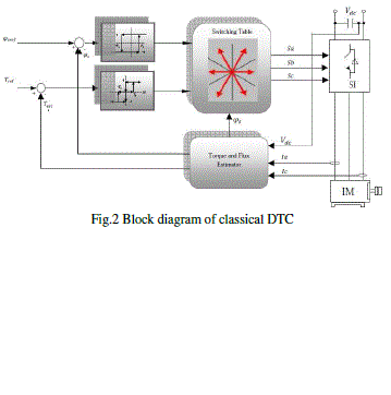
| DTC is an alternative method to flux-oriented control. However, in the standard version, important torque ripple is obtained even at high sampling frequencies. Moreover, the inverter switching frequency is inherently variable and very dependent on torque and shaft speed. This produces torque harmonics with variable frequencies and an acoustic noise with disturbance intensities very dependent on these mechanical variables and particularly grating at low speed. The additional degrees of freedom (space vectors, phase configurations, etc.) provided by the multilevel inverter should, therefore, be exploited by the control strategy in order to reduce these drawbacks [6], [9]. |
| The basic model of DTC induction motor scheme is shown in Fig. 1. At each sample time, the two stator currents Isa and Isb and the DC bus voltage Vdc are sampled. Using the inverter voltage vector, the αβ, components of the stator voltage space vector in the stationary reference frame are calculated as follows. |
 |
| The αβ components of the stator current space vector are calculated using |
 |
| The stator flux is a function of the rotor flux which is provides from the flux observer |
 |
| Then the magnitude of the stator flux is calculated by |
 |
| The electromagnetic torque is calculated by |
 |
| The inverter switching states are determined by the torque and flux errors according to the sector determined. |
| A. Voltage Vector Selection: |
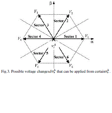
| Fig. 3 illustrates one of the 127 voltage vectors generated by the inverter at instant t=k, denoted by (central dot). The nextvoltage vector, to be applied to the load , can be expressed by |
 |
| Where ={vi|i=1, ..., 6}. Each vector vi corresponds to one corner of the elemental hexagon illustrated in gray and by the dashed line in Fig. 8. The task is to determine which will correct the torque and flux responses, knowing the actual voltage vector ,the torque and flux errors and , and the stator flux vector position (sector determined by angle θs). Note that the next voltage vector applied to the load will always be one of the six closest vectors to the previous ; this will soften the actuation effort and reduce high dynamics in torque response due to possible large changes in the reference. Table II summarizes vector selections for the different sectors and comparators output (desired φs and Te corrections). |
| To implement the DTC of the induction motor fed by a hybrid H-bridge multilevel inverter, one should determine at each sampling period, the inverter switch logic states as a function of the torque and flux instantaneous values for the selection of the space vector in the α–β frame. The proposed control algorithm was divided into two major tasks, which are independent and executed in cascade. |
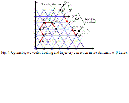
| 1) First task: It aims at the control of the electromagnetic state of the induction motor. The torque and flux instantaneous values and their variations will be taken into account for the space vector selection in the α–β. Once the space is chosen, the phase levels sequence can be selected. To ensure this task, one should detect the space vector position in the α–β frame (Qk at sampling time k). The algorithm must then select the next position Qk+1 to be achieved before next sampling instant k+1 (see Fig.4) in order to reduce voltage steps magnitude. Only one step displacement in the α–β frame is authorized per sampling period Ts. Hence, in the absence of inverter saturation, Qk+1 must coincide with one of the six corners of the elementary hexagon cantered at Qk. The same procedure will be carried out at the next period in order to determine the next trajectory direction, yielding Qk+2, which in turn will coincide with one of the six corners of the new elementary hexagon cantered at Qk+1. In case of inverter saturation (if Qk gives an unreachable point for Qk+1), a trajectory correction is necessary (see Fig. 4). In cases (2) and (3), the closest displacement direction is selected. Case (1) illustrates a particular situation in which no switching should be performed, since the nearest reachable trajectory goes roughly toward the opposite sense of the favored one given by the lookup table (see Table II). |
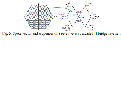
| 2) Second task: It exploits the degree of freedom related to the multilevel topology to choose the phase levels sequence that synthesizes the voltage vector selected previously. There are several phase levels sequences that are able to generate the same vector illustrated in Fig. 5; this degree of freedom can, therefore, be exploited to reduce voltage steps magnitude according to one of the following criteria: a) minimize the commutation number per period; b) distribute commutations for the three-phases per period; or c) choose a vector which minimizes the homo polar voltage. This task allows losses and torque ripple minimization. |
| Finally, the configuration of each phase will be selected and must be able to generate the phase levels. |
MATRIX CONVERTER
|
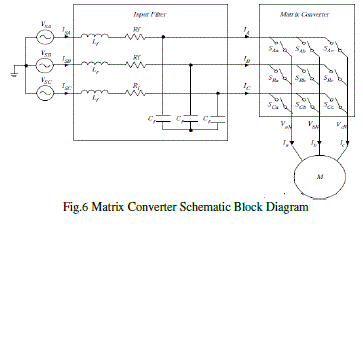
| The matrix converter has several advantages over traditional rectifier-inverter type power frequency converters. It provides sinusoidal input and output waveforms, with minimal higher order harmonics and no sub harmonics; it has inherent bi-directional energy flow capability; the input power factor can be fully controlled. Last but not least, it has minimal energy storage requirements, which allows to get rid of bulky and lifetime-limited energy-storing capacitors. But the matrix converter has also some disadvantages. First of all it has a maximum input output voltage transfer ratio limited to 87 % for sinusoidal input and output waveforms. It requires more semiconductor devices than a conventional AC-AC indirect power frequency converter, since no monolithic bi-directional switches exist and consequently discrete unidirectional devices, variously arranged, have to be used for each bi-directional switch. Finally, it is particularly sensitive to the disturbances of the input voltage system.Fig 6 shows a schematic block diagram of the matrix converter has a simple topology and a compact design due to the lack of DC-link capacitor for energy storage. |
| The three-phase matrix converter module includes nine bi-directional switches as shown in Fig.6. There are 27 switching configuration states, which mean 27 possible space vectors can be used to control IM and can be split respectively into 3 groups as shown in Table 1; in Group I, two output lines are connected to one of the other input lines; in Group II, all output lines are connected to a common input line; while in Group III, each output line is connected to a different input line. The corresponding output line-to-neutral voltage vector and input line current vector have fixed directions as represented in Figure 2. However, Group III is not useful. Only 18 non-zero space vectors in Group I (±1, ±2, …, ±9) and 3 zero space vectors in Group II (0a, 0b, 0c) can be usually employed in the modern control techniques for the matrix converter (such as the Space Vector Modulation, DTC methods, etc.). |
MATLAB MODELING AND SIMULATION RESULTS
|
| Here simulation is carried out in different conditions, in that 1. Proposed Symmetrical 5-Level Multilevel Inverter with Drive 2. Proposed A-Symmetrical 7-Level Multilevel Inverter with Drive 3. Proposed Symmetrical 7-Level Multilevel Inverter with Drive 4. Proposed A-Symmetrical 9-Level Multilevel Inverter with Drive 5. Proposed Symmetrical 11- Level Multilevel Inverter with Drive. |
| Case 1: Proposed Symmetrical 5-Level Multilevel Inverter with Drive |
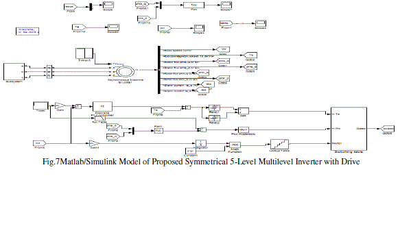
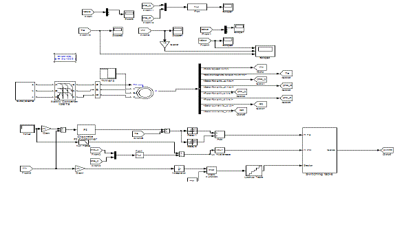
| Fig.7 shows the Matlab/Simulink Model of Proposed Symmetrical 5-Level Multilevel Inverter with Drive with Matlab/Simulink. |
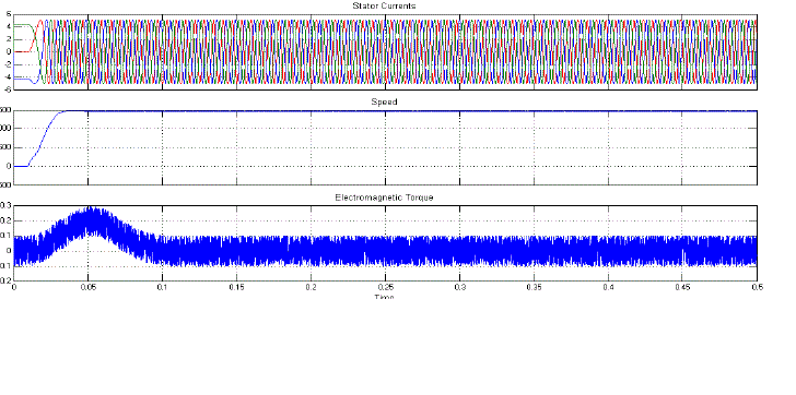
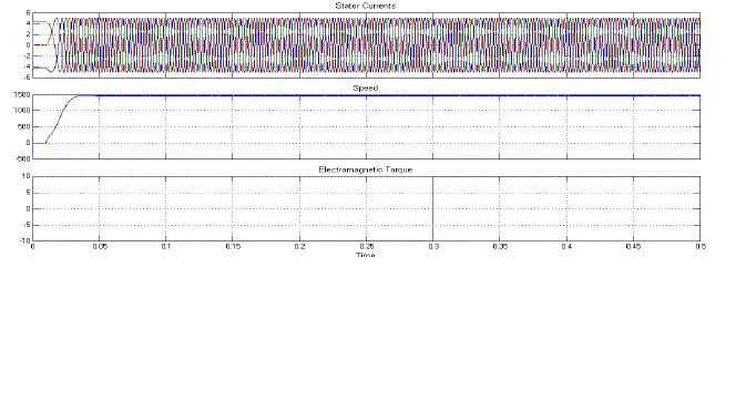
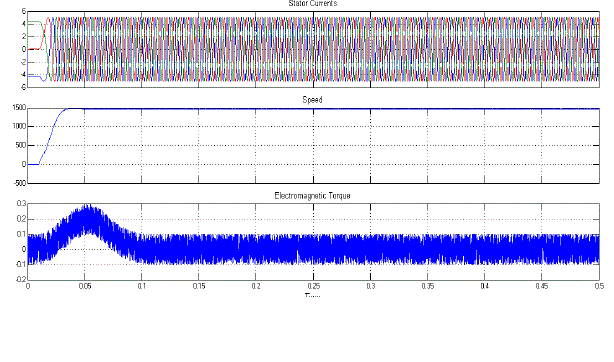
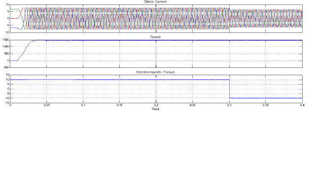
| Fig.8 shows the Stator Currents, Speed, and Electromagnetic Torque of Proposed Symmetrical 5-Level Multilevel Inverter with Drive. |
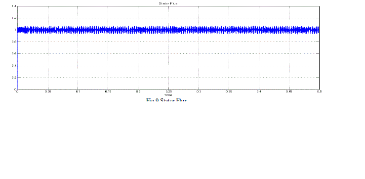
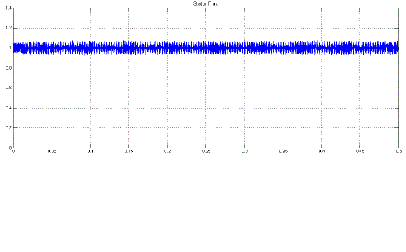
| Fig.9 shows the Stator Flux of Proposed Symmetrical 5-Level Multilevel Inverter with Drive. |
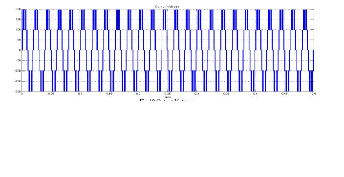
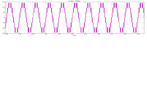
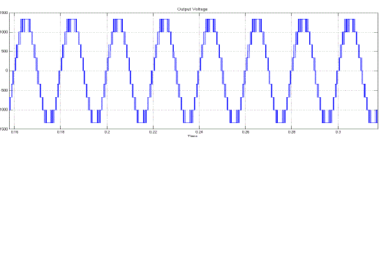
| Fig.10 shows the Output Voltage of Proposed Symmetrical 5-Level Multilevel Inverter with Drive. |
| Case 2: Proposed A-Symmetrical 7-Level Multilevel Inverter with Drive |
| Fig.11 shows the Stator Currents, Speed, and Electromagnetic Torque of Proposed A-Symmetrical 7-Level Multilevel Inverter with Drive. |
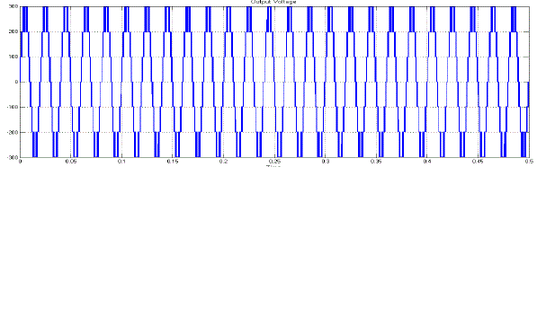
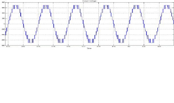
| Fig.12 shows the Output Voltage of Proposed A-Symmetrical 7-Level Multilevel Inverter with Drive. |
| Fig.13 shows the Stator Flux of Proposed A-Symmetrical 7-Level Multilevel Inverter with Drive. |
| Case 3: Proposed Symmetrical 7-Level Multilevel Inverter with Drive |
| Fig.14 shows the Stator Currents, Speed, and Electromagnetic Torque of Proposed Symmetrical 7-Level Multilevel Inverter with Drive. |
| Fig.15 shows the Output Voltage of Proposed Symmetrical 7-Level Multilevel Inverter with Drive. |
| Case 4: Proposed A-Symmetrical 9-Level Multilevel Inverter with Drive |
| Fig.16 shows the Stator Currents, Speed, and Electromagnetic Torque of Proposed A-Symmetrical 9-Level Multilevel Inverter with Drive. |
| Fig.17 shows the Output Voltage of Proposed A-Symmetrical 9-Level Multilevel Inverter with Drive. |
| Case 5: Proposed Symmetrical 11-Level Multilevel Inverter with Drive |
| Fig.18 shows the Matlab/Simulink Model of Proposed Symmetrical 11-Level Multilevel Inverter with Drive using matrix converter with Matlab/Simulink. |
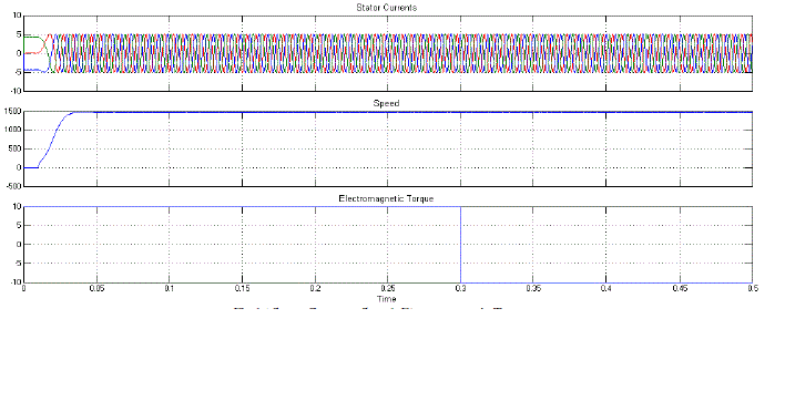
| Fig.19 shows the Stator Currents, Speed, and Electromagnetic Torque of Proposed Symmetrical 11-Level Multilevel Inverter with Drive. |
CONCLUSION
|
| A direct torque control (DTC) and DTC with Matrix converter (DTC_MC) are proposed and compared, the torque ripples of DTC_MC method are as small as that of in DTC. The DTC_MC is reinforced by modifying the torque error hysteresis comparator in order to distinguish between small, medium and large positive and negative torque errors. The simulation results prove the excellent transient torque response for both proposed methods. The DTC_MC method has a better performance. Since the torque control and torque ripples reduction was the main goal, the speed and steady response of DTC_MC method possesses less ripples in compare DTC.The technique is used to improve the level of the inverter and extends the design flexibility and reduces the ripples in torque. Indeed, this paper proposed symmetrical and asymmetrical arrangements of five- and seven-levels as well as nine-level, eleven-level H-bridge inverters have been compared in order to find an optimum arrangement with lower switching losses and optimized output voltage quality. In addition, torque ripples are greatly reduced: asymmetrical multilevel inverter enables a DTC solution for high-power induction motor drives. |
Tables at a glance
|
|
|
Figures at a glance
|
 |
 |
 |
 |
 |
| Figure 1 |
Figure 2 |
Figure 3 |
Figure 4 |
Figure 5 |
 |
 |
 |
 |
 |
| Figure 6 |
Figure 7 |
Figure 8 |
Figure 9 |
Figure 10 |
 |
 |
 |
 |
 |
| Figure 11 |
Figure 12 |
Figure 13 |
Figure 14 |
Figure 15 |
 |
 |
 |
 |
 |
| Figure 16 |
Figure 17 |
Figure 18 |
Figure 19 |
Figure 20 |
|
References
|
- L. G. Franquelo, J. Rodriguez, J. I. Leon, S. Kouro, R. Portillo, and M. A. M. Prats, “The age of multilevel converters arrives, ”IEEE Ind.Electron. Mag., vol. 2, no. 2, pp. 28–39, Jun. 2008.
- K.N.V Prasad, G.Ranjith Kumar, T. VamseeKiran, G.Satyanarayana., "Comparison of different topologies of cascaded H-Bridge multilevelinverter," Computer Communication and Informatics (ICCCI), 2013 International Conference on , vol., no., pp.1,6, 4-6 Jan. 2013.
- M. F. Escalante, J. C. Vannier, and A. Arzande, “Flying capacitor multilevel inverters and DTC motor drive applications,” IEEE Trans.Ind.Electron.vol., vol. 49, no. 4, pp. 805–815, Aug. 2002.
- T. Ishida, K. Matsuse, T. Miyamoto, K. Sasagawa, and L. Huang, “Fundamental characteristics of five-level double converters with adjustableDC voltages for induction motor drives, ”IEEE Trans. Ind. Electron., vol. 49, no. 4, pp. 775–782, Aug. 2002.
- K.N.V. Prasad, G.Ranjith Kumar, Y.S. Anil Kumar, G. Satyanarayana, "Realization of cascaded H-bridge 5-Level multilevel inverter asDynamic Voltage Restorer," Computer Communication and Informatics (ICCCI), 2013 International Conference on , vol., no., pp.1,6, 4-6 Jan.2013.
- F. Khoucha, M. S Lagoun, K. Marouani, A. Kheloui, and M. E. H. Benbouzid, “Hybrid cascaded H-bridge multilevel inverter induction motordrive direct torque control for automotive applications, ”IEEE Trans. Ind. Electron., vol. 57, no. 3, pp. 892–899, Mar. 2010.
- C. Rech and J. R. Pinheiro, “Impact of hybrid multilevel modulation strategies on input and output harmonic performance, ”IEEE Trans.Power Electron., vol. 22, no. 3, pp. 967–977, May 2007.
- G.Satyanarayana., K.N.V Prasad, G.Ranjith Kumar, K. Lakshmi Ganesh, "Improvement of power quality by using hybrid fuzzy controlledbased IPQC at various load conditions," Energy Efficient Technologies for Sustainability (ICEETS), 2013 International Conference on , vol.,no., pp.1243,1250, 10-12 April 2013.
- F. Khoucha, M. S. Lagoun, A. Kheloui, and M. E. H. Benbouzid, “Symmetrical and asymmetrical H-bridge multilevel inverter for DTCinduction motor drive automotive applications,” inProc. IEEE IECON2009,Porto,Portugal, Nov. 2009, pp. 1344–1349.
- G. Lakpathi, S. ManoharReddy,K. Lakshmi Ganesh, G. Satyanarayana“ An Effective High Step-Up Interleaved DC-DC ConverterPhotovoltaic Grid Connection System” International Journal of Soft Computing and Engineering (IJSCE), Vol-3, Issue-4, p.p. 156-162, Sep,2013.
- S. Lu, K. A. Corzine, and M. Ferdowsi, “A unique ultra capacitor direct integration scheme in multilevel motor drives for large vehiclepropulsion,” IEEE Trans. Veh. Technol., vol. 56, no. 4, Part 1, pp. 1506–1515, Jul. 2007.
- G. Satyanarayana, K.Lakshmi Ganesh , CH. Narendra Kumar, N. SrinivasaRao “Realization of Hybrid Active Power Filter Applied to BLDCMotor Drive Using Dual Instantaneous Power Theory”, International Journal of Engineering Associates, Vol-1, Issue 3, p.p. 32-37, Feb, 2013.
- G.Gopal, B.Shankaraiah, M.Chinnalal, K.Lakshmi Ganesh, G.Satyanarayana, D.SreenivasaNaik“A New topology of Single-Phase Seven-Level Inverter with Less Number of Power Elements for Grid Connection” International Journal of Innovative Technology and ExploringEngineering (IJITEE), Vol-3, Issue-4, p.p. 79-84, Sep, 2013.
|