ISSN ONLINE(2319-8753)PRINT(2347-6710)
ISSN ONLINE(2319-8753)PRINT(2347-6710)
A. Arulsankar1, K. Kulasekarapandian1, S. Jeya1, S. Jayanthi2 and B. Sundaresan1
|
| Related article at Pubmed, Scholar Google |
Visit for more related articles at International Journal of Innovative Research in Science, Engineering and Technology
The structural, electrical and morphological properties of Poly (Methyl Methacrylate) (PMMA) complexed with magnesium perchlorate (Mg(ClO4)2) were investigated. The effect of addition of nanofiller, fumed silica (SiO2) (1.29 nm) was also studied. The analysis of Fourier Transform Infrared Spectroscopy (FTIR) spectra of the samples revealed that there was complexation between PMMA and Mg(ClO4)2. It also revealed the plasticizing action of fillers in the electrolyte and hence the structural changes of systems studied. XRD Studies indicated the better dissolution of Mg(ClO4)2 in PMMA matrix. The amorphous nature of the polymer electrolyte has been enhanced by the incorporation of nano sized SiO2. Analysis by impedance studies showed that the two conductivity maxima have been observed for 2 and 10wt% of SiO2 added system. The morphological changes have been observed through AFM studies.
Keywords |
| Poly (Methyl Methacrylate), Magnesium perchlorate, Silica, AC impedance studies, FTIR |
INTRODUCTION |
| Solid polymer electrolytes (SPEs) have drawn much interest among researchers due to their high specific energy, good reliability, high ionic conductivity, solvent-free condition, light weight and wide electrochemical stability windows [1 – 4]. Among various SPEs, polyethylene oxide (PEO) – Lithium salt (LiX) complexes [5] were most studied, since they possess advantages like high energy density, better cycle ability and safety to be used as an electrolyte in solid – state batteries [6]. But PEO based SPEs exhibit low ionic conductivity at ambient temperature which limits their applications [7]. |
| A number of researchers [8, 9] have demonstrated that, improved ionic conductivity is achieved by the inclusion of plasticizer into the polymer matrix. But they suffer several drawbacks like decomposition, volatilization, and also the deterioration of the mechanical properties. |
| Another way to increase the ionic conductivity is done by the inclusion of nano fillers like SiO2, Al2O3, TiO2 , MgO, SnO2, ZnO, CuO, CdO and ZrO2 [10]. In addition, the Lewis acid – base interactions between the polar surface groups of the nano fillers and the electrolyte ionic species yield a greater degree of salt dissociation through the formation of ionic – filler complex. |
| Poly (methyl methacrylate) (PMMA), has been chosen as a host polymer for the present study, due to its outstanding chemico-physical properties which represent a particularly suitable polymer component for the embedding of both microscopic and nanoscopic functional inorganic fillers. The wide use of such a matrix has to be traced back to the favourable combination of chemical and physical properties and easy processing. It has been well established that PMMA acts as a good host material for dielectric materials. PMMA-Ceramic composites exhibit remarkably low dielectric loss at high frequency, which makes them potential material for the capacitors in high frequency application. It is an amorphous polymer and it is a colorless, transparent, plastic with an excellent life period and good mechanical properties. |
| Fumed silica as a filler is of special interest because of its branched primary structure and the ability to tailor the surface functionalities. Composite Polymer Electrolytes based on fumed silica were shown to be highly transparent in the visible region and to have a wide electrochemically stable potential window [11]. |
| Appetecchi et al. , studied the kinetics and stability of the lithium electrode in PMMA-based gel electrolytes [12]. Sekhon et al., reported the transport properties of lithium electrolytes gelled with PMMA. [13]. When PMMA is combined with inorganic materials such as Silica (SiO2), Titania (TiO2) or zirconia (ZrO2) at the nanometer level, the resulting hybrid materials have high strength and thermal stability [14]. Addition of filler grains also gives rise to the inhibition of polymer recrystallization and decreases the glass transition temperature (Tg) of the solid polymer electrolytes [15]. |
| It has been reported that, gel polymer electrolyte, PMMA–Na(ClO4)–4wt% SiO2, showed a maximum conductivity of 3.4x10⁻³ S cm-1 [16]. |
| Nevertheless, lithium-ion batteries are relatively expensive and suffer from some safety limitations. Magnesium-based rechargeable battery system has attracted attention due to its performance capabilities that are close to those of lithium-based alternatives [17–19]. Magnesium is an attractive anode material for batteries of high specific energy because it has a low electrochemical equivalence (12.15 g equiv.−1) and a considerably negative electrode potential (−2.3V versus SHE). In addition, it is cost effective due to natural abundance and safer than lithium. The use of magnesium as a negative electrode in aqueous primary and rechargeable batteries has been reported [20] and hence Mg(ClO4)2 is chosen as the electrolyte for the present study. |
| Though lot of lithium salts have been studied to enhance the conductivity of PMMA based solid polymer electrolytes, here it is attempted to study the conductivity of the non lithium salt Mg(ClO4)2 and the effect of addition of 1.29 nanometre sized silica (SiO2) particles. |
EXPERIMENTAL |
| Materials and Methods |
| The polymer electrolyte complexes PMMA-Mg(ClO4)2 and PMMA- Mg(ClO4)2-SiO2 are prepared by solvent casting technique using tetrahydrofuran as solvent. The prepared samples are analyzed to understand the effect of addition of SiO2, to PMMA-Mg(ClO4)2 complexes, on the structural and electrical properties of the complexes. The samples are characterized using FTIR, XRD, AC impedance and AFM techniques. |
| The FTIR spectra are recorded by a SHIMADZU-8400S, FTIR Spectrometer, in the region of 400 – 4000 cm-1, with a signal average of 20 scans at a resolution of 4 cm-1. X-ray diffraction (XRD) measurements are carried out with XPERT-PRO System. Conductivity studies were carried out by AC Impedance Analyzer Model PSM 1735 (10μHz-35MHz) supplied by Newtons 4th Ltd., UK. 3D AFM images were taken to show the morphological changes occurred at the surface of the samples at microscopic level. |
RESULTS AND DISCUSSION |
| A. FTIR |
| Infrared spectroscopy is a powerful tool for characterizing the organic-inorganic composite materials. Figure 1 shows the infrared spectra of PMMA - Mg(ClO4)2 - SiO2 system. The peak assignments of these spectra are given. |
| The FTIR spectrum of PMMA is shown in figure 1a. The peaks at 2966, 1726, 1456, 1122 and 1192 cm-1 are assigned to CH3 asymmetric stretching, C=O symmetric stretching, CH3 asymmetric deformation, C-O-C single bond symmetric stretching and O-CH3 symmetric stretching modes respectively. |
| Figure 1b shows the FTIR spectrum of Mg(ClO4)2. It has a contact ion pair vibration at 627 cm-1. The peaks at 1100 and 1632 cm-1 are assigned to ClO4 - asymmetric stretching and internal vibrational mode. Mg2+ … O solvent coordinated vibration appeared at 941 cm-1[21]. |
| From the FTIR spectrum of PMMA-Mg(ClO4)2, as given in figure 1c, the addition of Mg(ClO4)2 to PMMA downshifts the C=O peak from 1672 to 1650 cm-1. The downshift of this peak is due to the weak electrostatic attraction between the cation and the carbonyl group, which is the highly reactive group of PMMA [22]. |
| The peak due to CH3 asymmetric deformation at 1456cm-1 downshifts to 1439cm-1 for the polymer electrolyte system. The peak at 1192cm-1 due to O-CH3 symmetric stretching of PMMA is upshifted to 1200 cm-1 after the addition of Mg(ClO4)2 to PMMA which confirms the complex formation between PMMA and Mg(ClO4)2 . The peak due to free ClO4 - ion is shifted from 627 cm-1 to 626 cm-1 for the electrolyte added system. Further new peaks appearing at 2387, 2291, 2048 and 987 cm-1 confirm the complex formation. |
| From the FTIR spectrum of pure Nanosized SiO2, as given in figure 1d, the peak at 1122 cm-1 is assigned to Si-O-Si asymmetric stretching. The peaks at 808 cm-1 and 465 cm-1 are attributed to Si-O4 tetrahedron ring stretching and O-Si-O deformation of SiO2 respectively [23]. |
| Figure 1e, shows the FTIR spectrum of 10 wt% SiO2 added PMMA-Mg(ClO4)2 system. The peak assignments for 10wt% of nano-silica is discussed in detail, because, it achieves the maximum ionic conductivity compared to other wt% of nano-silica added systems. |
| The peak at 1717 cm-1 for the Mg(ClO4)2 added PMMA, due to the C=O symmetric stretching upshifts to 1726 cm-1. This demonstrates that the polymer carbonyl (>C=O) groups are involved in the direct interaction with the nanosilica filler, which has also been observed for the polymer electrolyte samples by the earlier investigations [23]. The peak at 1439 cm-1 assigned to CH3 asymmetric deformation is positively shifted to 1442 cm-1 for SiO2 added system. |
 |
| Fig. 1 FTIR spectra of (a) pure PMMA (b) pure Mg(ClO4)2 (c) PMMA - Mg(ClO4)2 complex (d) pure SiO2 (e) PMMA - Mg(ClO4)2 - 10 wt% SiO2 |
| The peak due to ClO4 - ion at 626 cm-1 gets shifted to 622cm-1. The peak due to O-CH3 symmetric stretching at 1200 cm-1 is shifted to 1150 cm-1 for 10 wt% filler added system. Further the peak due to Si-O-Si asymmetric stretching at 1122 cm-1 is shifted to 1150 cm-1 for 10 wt% SiO2 added system. Hence the changes in the FTIR result provide convincing evidence for polymer-filler interaction [24]. |
| B. XRD |
| Figure 2 shows the XRD patterns of the nanocomposite polymer electrolytes. The XRD pattern of pure PMMA in figure 2a shows a broad peak at 2θ =140 and at 2θ = 270, which indicates the amorphous nature of PMMA. The peak at 140 was broad and intense whereas the other one was broad, but with lesser relative intensity. |
| The XRD pattern of Mg(ClO4)2 in figure 2b shows sharp peaks at 220, 230, 320 and 470 along with many small Bragg’s peaks. The peaks at 220, 230 and 320 are shifted to 240, 280 and 340 in PMMA - Mg(ClO4)2 complex as shown in figure 2c. The addition of Mg(ClO4)2 to PMMA has led to the disappearance of the peak at 140 corresponding to PMMA. Further, some of the Bragg’s peaks due to Mg(ClO4)2 disappeared in the electrolyte added system. This indicated the better dissolution of Mg(ClO4)2 in PMMA and hence the complex formation between PMMA and Mg(ClO4)2.Figure 2d shows the XRD pattern of SiO2 which shows a single peak at 220 . The XRD pattern of 10 wt% SiO2 added system is shown in figure 2e. When 10wt% of nano-sized SiO2 was added to PMMA-Mg(ClO4)2, the Bragg’s peak observed for PMMA at 270 was further broadened which indicates the increase in degree of amorphicity of PMMA – Mg(ClO4)2 – SiO2 system [25]. |
| The increased amorphous nature of the nano-composite polymer electrolyte has led to the enhancement of ionic conductivity. It can also be pointed out through XRD studies that the added SiO2 has acted as “solid plasticizer” to PMMA-Mg(ClO4)2 polymer electrolyte system. |
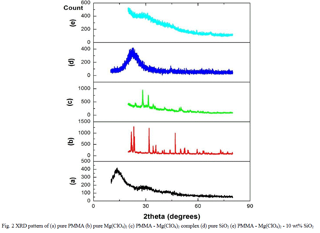 |
| Fig. 2 XRD pattern of (a) pure PMMA (b) pure Mg(ClO4)2 (c) PMMA - Mg(ClO4)2 complex (d) pure SiO2 (e) PMMA - Mg(ClO4)2 - 10 wt% SiO2 |
| C. Ionic Conductivity |
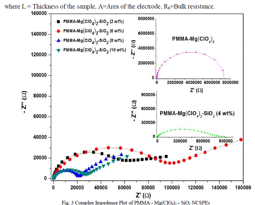
| Figure 3 shows the complex impedance plot for PMMA-Mg(ClO4)2 and PMMA-Mg(ClO4)2 with different compositions of SiO2 (2wt% - 10wt%) at room temperature (302 K). Depressed semicircle, as given in figure 3, at high frequency side, and an inclined spike at lower frequency side, together are characteristic behaviour of ionically conducting polymer electrolyte with blocking electrodes [26]. |
| The semicircle is due to the parallel combination of bulk resistance (due to the migration of ions) and bulk capacitance (due to the immobile polymer chains). The presence of the depressed semicircle reveals the non-Debye nature of the sample [6] due to the potential well for each site, through which the ion transport take place, not being equal. The inclined spike represents the formation of double layer capacitance at the electrode-electrolyte interface due to the migration of ions at low frequency [27]. Furthermore, the inclination of the spike at an angle less than 90o to the real axis is due to the roughness of the electrode-electrolyte interface [28]. |
| The ionic conductivity of the NCSPEs has been calculated by the following relation, |
 |
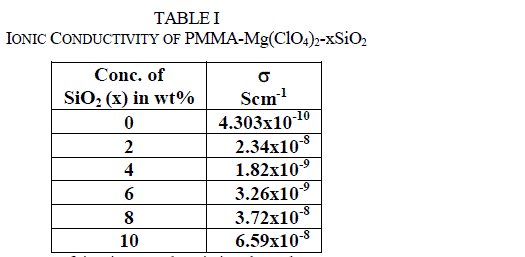 |
| There is an initial sudden increase of ionic conductivity by almost two orders of magnitude when 2 wt% of SiO2 is dispersed in the polymer electrolyte system, followed by another maxima at 10 wt% of SiO2. The conductivity decreases on further addition of silica nanoparticles. Two such maxima feature in the conductivity variation with respect to filler content for solid polymer electrolytes have been reported. A maximum conductivity of 2.34x10⁻⁸ Scm−1 is observed for the nanocomposite solid polymer electrolyte dispersed with 2 wt% SiO2 nano filler. Such higher values of conductivity are attributed to the higher amorphicity of the materials and space charge defects generated around SiO2 nanoparticles in the polymer matrix. The first conductivity maximum, which is observed at a lower content (2 wt%) of SiO2 nanoparticles, is associated with the generation of free ions followed by their pairing/re-association. The second conductivity maximum is related to the composite effect and is explained on the basis of the formation of a high conducting interfacial layer between the SiO2 nanoparticles and polymer electrolyte due to the instantaneous presence of SiO2:ClO4 − species [29–32]. As discussed above, such charged layers (which induce a local electric field) are responsible for the generation of free ions for conduction and their mobility, and hence enhance the overall electrical conductivity. |
| D. AFM |
| The surface morphology of PMMA, PMMA-Mg(ClO4)2 and nanofiller SiO2 dispersed PMMA-Mg(ClO4)2 materials are examined by Atomic Force Microscope and are given in figure 4. |
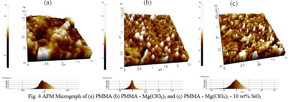 |
| Comparing figure 4a and figure 4b, a definite morphological change has been observed after the introduction of Mg(ClO4)2 salt to PMMA, which confirms the complex formation between polymer and salt as observed through FTIR studies. The height histogram of surface morphology of PMMA has a distorted Gaussian like distribution reflecting the important roughness information of the surface feature. The surface roughness of PMMA was 22.5 nm. After the introduction of Mg(ClO4)2 into the PMMA matrix, the complex has the surface roughness of 6.386 nm. This confirms the morphological change in the complex. The side view of the AFM of nano sized SiO2 added PMMA - Mg(ClO4)2 system (Figure 4c) exhibited a mountain valley pattern with wider distribution observed from the height histogram, when compared with that of filler free system (Figure 4b). For this system, the height histogram of surface morphology showed a distorted Gaussian distribution and the roughness is found to have increased to 7.816 nm. This reveals that the amorphicity of SiO2 added system has increased over SiO2 free system which would support the transport of Mg2+ ions through the PMMA matrix. This substantiates the observed maximum ionic conductivity of the SiO2 added system [33]. This assures the occurrence of intermolecular interaction among the species involved and hence the structural modification which facilitates the fast Mg2+ ion transport as mentioned in the ionic conductivity studies. The presence of small voids in the micrographs of filler added system is attributed to the rapid solvent evaporation from the cast film during the sample preparation [34]. |
CONCLUSION |
| The analysis of FTIR spectra of the samples revealed that there was complexation between PMMA and Mg(ClO4)2. It also revealed the plasticizing action of nanofiller, fumed silica, in the electrolytes and hence accounted for the structural changes in the systems studied. XRD patterns of the samples complemented the results obtained by FTIR analysis. |
| AC impedance spectroscopic studies threw light on the ionic conductivity of the samples studied. The DC ionic conductivity was determined from complex impedance plot. Two ionic conductivity maximum were obtained. The first conductivity maximum is associated with the generation of free ions followed by their pairing/re-association. The second conductivity maximum is related to the formation of a high conducting interfacial layer between the SiO2 nanoparticles and polymer electrolyte due to the instantaneous presence of SiO2:ClO4 − species. The increase in ionic conductivity with the addition of filler was attributed to the enhancement of amorphicity in polymer electrolyte matrix, thereby resulting in the promotion of more channels for Mg2+ ion transport. AFM pictures assured the occurrence of intermolecular interaction involved and hence resulting in the structural modification so as to facilitate the fast Mg2+ ion transport. The height histogram of surface morphology and roughness values of AFM micrographs confirmed the conclusions drawn through FTIR, XRD and AC impedance studies. |
ACKNOWLEDGMENT |
| The author wishes to thank Mr. K. Kulasekarapandian, Mrs. S. Jeya and Ms. S. Jayanthi for their moral support and immense help in analysing the results. The author wishes to thank the Management, Ayya Nadar Janaki Ammal College for providing necessary infrastructure, instrumental and computational facilities to carry out this work. |
References |
|