ISSN ONLINE(2319-8753)PRINT(2347-6710)
ISSN ONLINE(2319-8753)PRINT(2347-6710)
Naveena M1, Dr. Suresh P M2
|
| Related article at Pubmed, Scholar Google |
Visit for more related articles at International Journal of Innovative Research in Science, Engineering and Technology
Modal analysis is the study of the dynamic properties of structures under vibrational excitation. Modal analysis is the field of measuring and analysing the dynamic response of structures, when excited by an input. The modal analysis of the centrifugal pump is performed using FEM technology to find the centrifugal rotor natural frequencies. To meet the higher target of power, machines have to run at higher speeds. The pump shaft will be subjected to higher lateral and torsional vibrations because of gyroscopic effect and centrifugal force of the rotating elements mounted on the shaft. The resonance is produced when the rotor natural frequency coincides with operating frequency, the deflection of the rotor will be maximum. To avoid resonance condition, it is necessary to evaluate all stiffness and damping coefficients of wear rings, mechanical seals, throttle seals and bearings. In this work an attempt is made to evaluate the Lateral critical speeds using ANSYS® software by plotting Campbell diagrams and is compared with theoretical calculations and RBTS (Rotor Bearing Testing Software). It is very difficult to eliminate all interference points in the system since there are so many external excitations. Forced response analysis was conducted to know the peak amplitudes at the resonance points. The rotor has been designed and analyzed by using the guidelines as per API 610 standards.
Keywords |
| Resonance, Centrifugal pump, FEM, Modal analysis, Vibration, Rotor dynamics, API. |
INTRODUCTION |
| Centrifugal pump consist of a stationary pump casing and a rotor with impellers consists of a rotating disc with several vanes attached. The main function of pump is to accelerate the fluid by pulse transmission while following the curvature of the impeller vanes from the impeller centre (eye) outwards. The pressure and kinetic energy increase at the impeller’s outer diameter and leaves the impeller into a diffuser or volute chamber. |
| To ensure the safety of the pump and associated plant components, the vibration and noise must be kept within certain limits. Typical reasons for pump failures can be diagnosed well in advance by applying the right kind of vibration testing, analysis, and evaluation criteria during pump monitoring or troubleshooting. |
II. MODEL FORMULATION |
| The lateral analysis is only concerned with the rotor part of the pump. The coupling between pump gear and motor is flexible so the gear and motor are not considered in the calculation and modeling. The details about rotor geometry, impellers mass, bearing properties and material properties are extracted from an existing model and the model is developed in ANSYS. |
a. Rotor Modeling |
| In ANSYS, elements for rotor dynamic model should be chosen based upon the criteria, i.e., it should support gyroscopic effects. BEAM188 is a two-node beam element in 3-D with tension, compression, torsion and bending capabilities is used to formulate the rotor. The entire rotor of centrifugal ANSYS model has the same level of discretization. |
b. Modeling of Impellers |
| MASS21 is used to formulate the impellers mass and inertia effects in the rotor. MASS21 is a point element and it is defined by a single node. The degrees of freedom of the element can be extended up to six directions: translations in the nodal x, y, and z directions and rotations about the nodal x, y, and z axes, the rotary inertia effects to the element is included in the element. The mass element adds only mass without any change in stiffness, contribute kinetic energy only. |
c. Modeling of Bearings And Supports |
| There are two bearings in the centrifugal pump that supports the rotor system in its lateral direction. The rotor is supported by mechanical structures like Hub wear rings, eye wear rings, central sleeve and throttle sleeve which acts as bearings. All bearings are modeled as linear isotropic bearings using COMBIN14 element. |
d. Loads |
| An unbalance distribution is assigned to the various parts of the rotor to study the unbalance response. These unbalances are represented as forces which are acting mutually perpendicular to the spinning axis. |
e. Constraints |
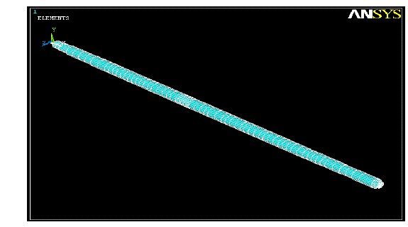
| All nodes at axial position are constrained axially and torsionally to avoid axial and twisting of the rotor respectively. The nodes at supports have displacement only in its represented plane (YZ plane). Therefore these nodes are also constrained in axial and torsional direction. The base nodes are fixed in all direction to represent that the model is connected to the rigid base. The FE model of the centrifugal rotor is shown in figure 1.1. |
 |
III. FINITE ELEMENT ANALYSIS |
| Modal analysis of the rotor was carried out to extract the natural frequencies of the pump. |
a. Undamped Analysis |
| Natural frequencies of rotor are extracted, when rotor is supported only at the bearings by considering the masses & inertias of all the mountings on rotor. Table 1.1 shows the natural frequencies of the undamped analysis of the rotor. |
 |
b. Analytical Approach |
| Analytical solution for the undamped analysis was done using the Rayleigh’s method. Rayleigh's method was applied to single-degree-of-freedom system, which is also applicable to discrete systems. The method assumes that, the system is conservative and at a principal mode the maximum potential energy of the system is equal to its maximum kinetic energy. |
 |
| The fundamental natural frequency of the rotor evaluated by Rayleigh’s method and ANSYS agree with each other. |
c. Damped Analysis |
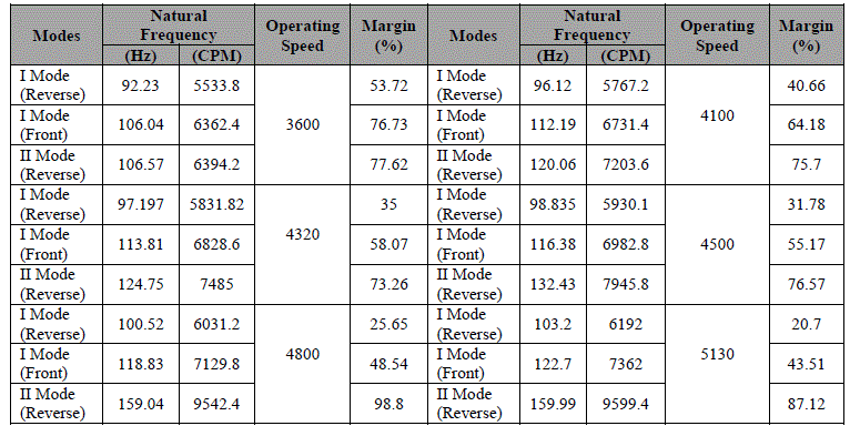
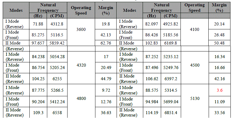
| The model was redefined with stiffness coefficients and damping coefficients for wear rings, central and throttle sleeve. The analysis has done for operating speeds 3600, 4100, 4320, 4500, 4800 and 5130rpm, the natural frequencies are tabulated in table 1.2 and 1.3 for the two conditions 1xAPI and 2xAPI. |
 |
 |
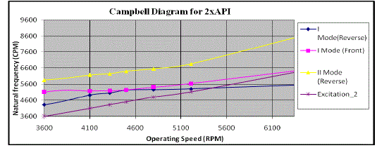
d. Campbell Diagram |
| The figure 1.2 and 1.3 shows the Campbell diagrams for 1xAPI and 2xAPI, natural frequency (cpm) vs. operating frequency (rpm). |
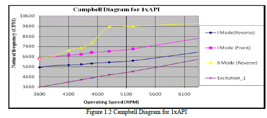 |
| From the figure 1.2 for 1xAPI calculations, all natural frequencies are within the acceptable region, that is percentage of margin between natural frequencies and operating speeds is more than 10% as defined in API 610. |
| From the figure 1.3 for 2xAPI calculations, the first reverse mode for 5130 is unacceptable, that is percentage of margin between natural frequency and operating speed is less than 10% at first reverse mode and unbalance response is needed for the first mode. |
e. Mode shapes for 5130 rpm |
| The 1st reverse and front modes for the 5130 rpm in 2xAPI condition are shown in figure 1.4. |
 |
f. Unbalance Response Analysis |
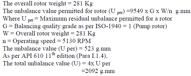
| Harmonic unbalance response analysis was performed to note the amplitude of vibrations at the critical points.To investigate this mode, total unbalance value is applied to the 2nd impeller station because the maximum deflection is observes near 2nd impeller position observed from figure 1.5. |
 |
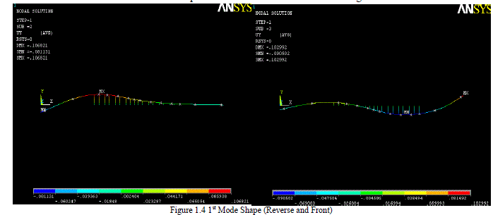 |
| The figure 1.5 shows the maximum deflection of the rotor at eye wear and hub wear rings from the applied unbalance at 2nd impeller station. |
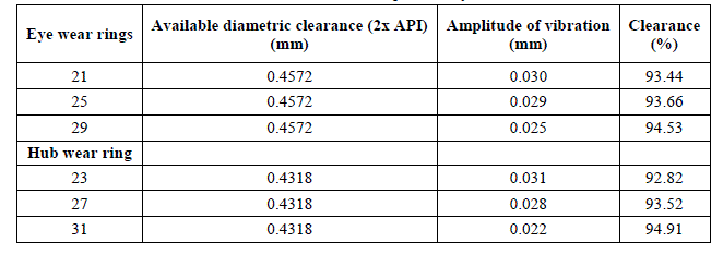 |
| The diametric clearance for the eye wear ring and hub wear ring are 0.4572 mm and 0.4318 mm respectively. From the table 1.4 the maximum amplitude of vibration is 7.18%, which is very less than 35% of the diametric clearance as defined by API 610 standards. |
IV. CONCLUSIONS |
| The main objective of this work is to build and perform rotordynamics analysis of Multi-stage centrifugal pump rotor using ANSYS. The results obtained from ANSYS, Analytical calculations and RBTS (Rotor Bearing Testing Software) are closer with each other. |
| The critical speeds for the centrifugal rotor obtained from Campbell diagram. From the Campbell diagram of 1x API, there is no resonance observed for all the operating speeds from 3600 RPM to 5130 RPM. But the first reverse mode for 2xAPI is closer to the pump operating speed, 5130 RPM. |
| The maximum amplitude of deflection of rotor for the applied unbalance loading is determined. The maximum amplitude of deflection is 7.12% which is less than 35% of the diametric clearance is obtained from unbalance response analysis as per API 610 guidelines. New clearance calculations are within the acceptable region as per API 610 standards. |
ACKNOWLEDGEMENT |
| I would like to thank Dr. C. Anil Kumar, professor, Dept of mechanical engineering, KSIT, Bangalore for his valuable support to carry out this work. |
References |
|