Keywords
|
| Algorithm State Machine (ASM), State Transition Table (STT), ROM, Linked-State Machine. |
INTRODUCTION
|
| Industrial intelligence suggests that a system of industrial process should be designed to exhibit well defined level of automation that should ensure:- |
| ïÃâ÷ Accurate monitoring of process involved. |
| ïÃâ÷ Self diagnosis in the event of fault. |
| In designing an intelligence process control system, a number of design approaches can be adopted. The level of intelligence built in the system determines the complexity of the machine, which determines the most suitable approach to use. |
| A simple microcontroller based design can achieve a very good level of automation and intelligence, but will lead to a lot of complexity with higher level of intelligence. A good approach to ease the design of complex systems is to break the system into a number of smaller systems (or modules) which can be linked together to give the desired intended system. |
II. A TYPICAL PROCESS CONTROL SYSTEM:
|
| Consider a system under design, where the parameters of interest are resource level and temperature. The process control system is expected to be equipped with a microcontroller based liquid level and temperature control system as well as automatic self-diagnostic features. This system is expected to serve an industrial set-up where a reservoir tank supplies a feeder tank from which water can now be dispensed or collected at a given temperature. As already stated above, the system should be equipped with some level of intelligence to enable it detect when a faulty condition occurs in the process flow and even suggest possible solution(s). i.e. it will have self diagnostic capabilities. |
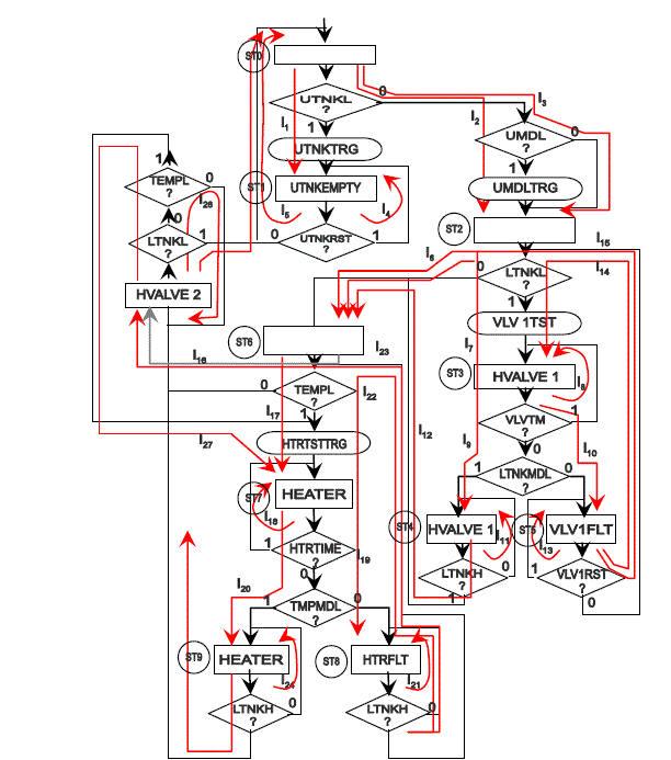
| The control algorithm for the above system is represented by the ASM chart of fig.1. The rectangular boxes in the ASM chart of fig.1 are state boxes with the state names indicated by the circular inscription of numbers by the side of each box. Other forms of outputs as indicated by the oblong boxes like the UMDLTRG, VLVTST1, HTRTSTTRG and UTNKTRG are conditional outputs each of which triggers a retriggarable monostable timer, whose output goes HIGH for the desired time interval. In effect, the ASM chart of fig.1 has six state outputs namely UTNKEMPTY, HVALVE 1, VLV1FLT, HEATER and HVALVE 2. In addition to the outputs, it also has four conditional outputs namely: - UTNKTRG, UMDLTRG, VLV1TST and HTRTSTTRG. It is important to note at this point, that it is on these four conditional outputs that the intelligence and self diagnostic features of this control system is anchored. |
| Figure 1 shows the ASM chart of the process control system with the link paths between states clearly indicated. The state codes of the system are generated with the help of the state map as shown below in tables 1a and 1b. |
| NOTE: With the help of the karnaugh map, the state map is obtained by inserting the state names serially in adjacent cells whose codes are chosen such that only one bit changes level as one progresses from one state of the control system to the other, as clearly represented in the resulting state assignment of Table 1b. |
III.THE STATE TRANSITION TABLE FOR THE INTELLIGENT SYSTEM
|
| As already stated, every ASM chart has an equivalent tabular representation known as state transition table (STT). The state transition table for the intelligent control system is presented in table 2. This is the tabular representation of the information contained in the ASM chart of fig 1. As usual, every data row under the table’s column headings corresponds to a link path. In effect, just as 28 link paths fully describe the ASM chart, so also does the STT have 28 data rows, one row per link path. |
| The state transition table for the above system has eight main column as follows;- |
| 1. The link path column featuring L1through L28. |
| 2. The input qualifies column; UTNKL, UTNKRST, UMDL, LTNKL, VLVTM, LTNKMDL, VLV1RST, TEMPL, HTRTIME, TMPMDL, HTRRST, UTEMP |
| 3. The present state name featuring ST0 through ST10. |
| 4. The present state code featuring DCBA=0000, 0001, 0011 e.t.c. |
| 5. The NEXT state name featuring ST0 through ST10. |
| 6. The NEXT state code featuring D`C`B`A`=0001, 0011, 0001, 0000 e.t.c. |
| 7. The state outputs; - UTNKEMPTY, HVLVE1, VLV1FLT, HEATER, HTRFLT, HVALVE 2. |
| 8. The conditional outputs;- UTNKTRG, UMDLTRG, VLV1TST and HTRTSTTRG. |
IV. FULLY EXPANDED STATE TRANSITION TABLE FOR THE INTELLIGENT SYSTEM
|
| The STT of table 1 expectedly contains a number of dashes under the columns headed by the input qualifiers. These dashes normally imply two things:- |
| 1. That the input qualifier above that column is not relevant for the transition being made in the link path where the dash appeared. |
| 2. That the input qualifier heading above the dash may be at logic 0 without affecting the control process at that material time. |
| Irrespective of the above design implications, it is important to accommodate all the possible combinations of logic values that can present its self in the design, considering the fact that to program a ROM, one need to define all (address) inputs including qualifiers as either 0 or 1 and none as a dash. |
| The state transition table (STT) of table 4.9 would be fully expanded when all the dashes on each row are given all possible combinations of logic values, leading to new rows in the STT, one for each combination of logic values for the dashes on that row. The implication here is that a total of 46080 rows would be required to fully expand the state transition table for the system |
| Ie. = (210 x 11) + (211 x 17) |
| = (1024 x 11) + (2048 x 17) |
| = 11264 + 34816 |
| No of rows required = 46080 |
| This is a very large number of rows to deal with manually and of course presents a very complex class C machine to design using this approach. Even when a software approach is used for generating the rows and obtaining the expanded STT, the complexity of the resulting machine will make it prone to possible and inevitable design errors as well as difficulty in maintainability. |
V. LINKED STATE MACHINE APPROACH
|
| It is possible to break the complex class C machine represented by the ASM chart of fig1 into simpler machines of class A category and then link the simple machines together to actualize the overall operation of the original complex machine. The machine can be separated into three simple machines as follows;- |
| 1. The upper tank control system. |
| 2. The lower tank control system. |
| 3. The heater control system. |
| Each of these three simple machines can now be developed with each fully automated and intelligent enough to handle diagnostic features. The three can then be linked together to effect full operation of the complex machine earlier conceived. |
VI.THE UPPER TANK CONTROL SYSTEM
|
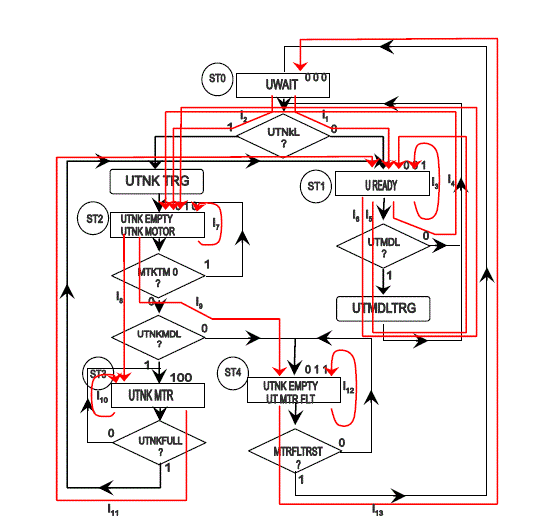
| The upper tank control system is designed to monitor the state of the upper tank that constantly supplies the lower distribution tank with resource whenever it is needed. It is therefore expected that the system should be able to monitor the state of the valve that controls its supply and report eventual fault conditions and also know when to supply resource to the lower tank. Control algorithm for the sub-system is represented by the ASM chart of fig2 with the link paths included. |
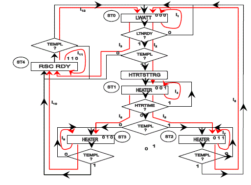
| Figure 2 shows the ASM chart representation of the Upper Tank control unit as a sub-unit of the original complex system being designed. |
VII. THE STATE TRANSITION TABLE FOR THE UPPER TANK CONTROL SYSTEM
|
| The state transition table for the upper tank control system, which is an equivalent tabular representation of the ASM chart of fig 2 is developed in table 2 with the necessary columns clearly stated. |
VIII. EXPANDED STATE TRANSITION TABLE FOR THE UPPER TANK CONTROL:
|
| As usual, for a ROM based design approach, the above STT for the Upper tank Control, should be expanded to accommodate all the possible states of the system based on the outputs of the input qualifiers. Table 3 shows the expanded STT for the upper tank control up to link-path L5 |
IX. THE LINK PATH ADDRESSABLE ROM STRUCTURE FOR THE UPPER TANK CONTROL SUB SYSTEM
|
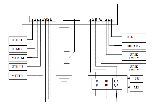
| Having obtained the Location Address and the Location Content for the upper tank control system form the expansion of the STT, the Hardware implementation of the upper tank control system can now be implemented using the link path addressable ROM structure model by setting up as ROM address, the value under LOCATION ADDRESS (HEX), one at a time and storing in each address the corresponding value under the LOCATION CONTENT (HEX) column. |
| Fig 3 shows in block diagram form, how the link path addressable ROM structure would be for the hardware implementation of the upper tank control system: |
| The same process as in 6,7,8 and 9 are repeated for the lower tank control system as well as the Heater control system. This means that the control algorithm, the algorithm state machine [ASM] chart, the state transition table (STT) as well as the fully expanded STT for the lower tank and the Heater systems is developed and from there the link path addressable ROM structure for the Hardware implementations designed. |
X. CONTROL ALGORITHM FOR THE LOWER TANK CONTROL SYSTEM
|
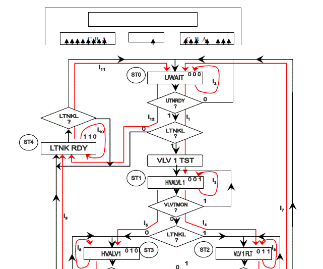
| The lower tank control system is linked to the upper tank control system such that it is intelligent enough to know when it is running out of resource and needed to be supplied by the upper tank. For it to be able to do this, it is equipped with enough intelligence to monitor the state of the upper tank as well as its own. It also has the capability of controlling the opening and closing of the supply valve to this effect and is able to carry out diagnostic check on the condition of the valves. The control algorithm to implement these features is presented as an ASM chart in figure4 |
| Figure 4 shows the ASM chart representation of the Lower Tank control unit as a sub-unit of the original complex system being designed. Also indicated are the various states and link paths that connect to constitute the logical operation of the sub-system. |
XI. STATE TRANSITION TABLE FOR LOWER TANK CONTROL
|
| From the ASM chart of figure 4, the STT for the Lower Tank Control is obtained as presented in table 4. The STT is expanded and the Hardware implemented exactly as in the case of the Upper Tank Control, using the link path addressable ROM structure model. |
XII. THE HEATER CONTROL SYSTEM;
|
| Once the lower tank is ready with resource, the overall system control is transferred to the heating section of the process. The heater control system like the other sub systems is equipped with adequate intelligence and self diagnostic features to ensure that the heater is always in good working condition. To this effect, the control algorithm for the Heater Control System is presented as an ASM chart of fig 5 while the state transition table is as shown in table 5. |
| Figure 5 shows the ASM chart representation of the Heater control unit as a sub-unit of the original complex system being designed. |
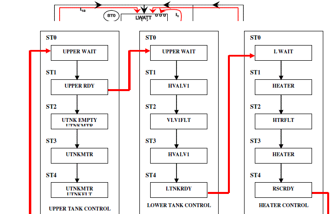
| Having developed the three subsystems as three separate simple machines, each fully equipped with adequate intelligence and self diagnostic features that will ensure complete functionality of the original complex system, the three simple machines can now be linked together to function as one complete system. Block diagram of the resultant Linked State Machine is shown in figure 6. |
| Figure 6 shows the block diagram of the resultant system as three simple sub systems logically linked together to achieve the originally intended system. |
XIV. CONCLUSION
|
| A detailed approach to the design of complex industrial process control system is presented to show how machine complexities can be simplified in design. Increase in the functional features of control systems increases the complexities of such system and when such is the case, it is possible to break such machine into subsystems of simpler machines which can now be linked together to actualize the full potential of the originally intended system. |
| The author presented a detailed example showing how giving parameters of interest in a typical process control system were monitored and controlled by separate simple control systems which are now linked together to bring about a complete process control system. |
| Although link-state machine approach in design of process control systems suggests the development of multiple systems with implications of higher cost of production and resource usage, it is a very efficient way of dealing with machine complexities which would have been very difficult to handle |
Tables at a glance
|
 |
 |
 |
 |
 |
| Table 1 |
Table 2a |
Table 3a |
Table 4 |
Table 5 |
|
| |
Figures at a glance
|
 |
 |
 |
| Figure 1 |
Figure 2 |
Figure 3 |
 |
 |
 |
| Figure 4 |
Figure 5 |
Figure 6 |
|