Keywords
|
| FACTS, Jacobian, Newton-Raphson, SSSC, TCSC |
INTRODUCTION
|
| The contol of an AC power in real time is involved because power flow is a function of the transmission line impedance, the magnitude of sending end and receiving end voltages, and the phase angle between these voltages. Years ago electric power systems were relatively simple and were designed to be self-sufficient. Furthermore, it was generally understood that Ac transmission systems could not be controlled fast enough. Transmission systems were designed with fixed or mechanically switched series and shunt reactive compensators, together with voltage regulating and phase Shifting transformer tap changer, to optimize line impedance, minimize voltage variation and control power flow under steady state or slowly changing load conditions. All these resulted in the under utilization of transmission systems. |
| During the last two decades, advances have been made in high power semiconductor device and control technologies. Hingorani proposed the concept of Flexible AC Transmission Systems or FACTS, which includes the use of high power electronics, advanced control centers, and communication link to increase the usable power transmission capacity. The possibility that current through a line can be controlled at a reasonable cost enables a large potential of increasing the capacity of existing lines with larger conductors and use of one of the FACTS controllers enable corresponding power to flow through such lines under normal and contingency conditions |
| The advent of flexible ac transmission systems (FACTS) devices has given a system operator additional leverage to control a power system. While FACTS devices like static var compensator (SVC) and thyristor controlled series compensator (TCSC) are variable reactance devices based on thyristors, the new generation of devices like static synchronous compensator (STATCOM), static synchronous series compensator (SSSC), unified power flow controller (IPFC), and interline power flow controller (IPFC) are based on voltage source converter (VSC) topology. STATCOM and SVC are shunt connected; SSSC,IPFC, and TCSC are series connected; and UPFC is a hybrid connected (i.e., have components connected both in series and shunt) FACTS device. |
| A. Formulation of Equations |
| ïÃâ÷ Choice of state variables (nodal voltages and angles in conventional load flow.) |
| ïÃâ÷ Choice of control/specified variables(shunt real and reactive power injections in a conventional load flow) |
| These choices are dictated by the basic operating characteristics, control, and limits of the devices. The reader is referred to a paper by Arabi and Kundur [3] for an exhaustive description of capabilities and limits of various devices |
| B. Methods of Solution |
| ïÃâ÷ Simultaneous or unified method: In this method, all equations are combined in to one set of algebraic equation.A Jacobian matrix is then constructed and Newton method is used to solve these equations. However, it may be inconvenient to implement as the incorporation of a FACTS device requires significant modifications in existing load flow programs |
| ïÃâ÷ Sequential or alternating method: In this method the equations are separated into those corresponding to the FACTS device specifications and the rest of the power balance equations. The equations are solved separate$ and sequentially. This method allows for relatively minor modification of the existing software. The conventional load flow formulation is retained as a subpart of the main algorithm |
| Load flow formulation and solution methodology for series FACTS devices in the previous literature mainly pertains to variable series reactance. Noroozian and Anderson [8] use real power flow as a specified variable and the reactance of a TCSC as a state variable. Two coupled load flow and line flow equations are solved sequentially- First one load flow solution is carried out by NR method by using the usual Jacobian matrix- The line power flow equation is then solved iteratively using the sohtrion of thc load flow equations to get updated values of series compensating reactance. These variables are used to carry out next load flow solution. The procedure is repeated till both solutions converge. In the method proposed by Fuerte_Esquivel and Acha [4], for each controllable series reactance, one extra line flow mismatch equation is augmented to the original NR load flow equations along with one extra state variable- It is observed that this unified approach is more robust and convergence is obtained within half the number of iterations as that required by the sequential approach. Gotham and Heydt [9] consider an extra fictitious bus for which real power specification is given However, the reactive power specification and voltage magnitude at that. bus are not known and are obtained from another set of nonlinear equations, which are solved separately. |
| Here formulation of load flow equations for series devices like SSSC and TCSC, using dual state variables (current magnitude and angle) and dual control variables (injected series real power and series voltage in quadrature with the current ) is used. |
II. FORMULATION OF EQUATIONS WITH FACTS DEVICES
|
| A. List of Symbol |
| Pi –Real power at bus i |
| Qi – Reactive power at bus i |
| Pser-Series injected real power |
| Qser-Series injected reactive power |
| V, V -Bus voltage magnitude |
| I-Magnitude of current flowing through a branch |
| δ- phase angle of bus voltage |
| ïÿýïÿýïÿýïÿýïÿýïÿý -Magnitude of Yij element in bus admittance matrix |
| γij- Angle of Yij element in bus admittance matrix |
| β- Phase angle of current flowing through a branch |
| n- Total number of buses |
| nj –Set of bus connected to bus j where series FACTS devices are connected |
| rj- set of branches connected to bus j where series FACTS devices are connected |
| VR –voltage n quadrature with the line current injected by the series device |
| IRj- Reactive current at the jth node |
| B. Formulations of Equations with Series Connected FACTS Devices |
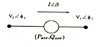
| Consider a series FACTS controller as shown in fig.1. The real power and the voltage in quadrature with the line current injected by the series devices are given by |
 (1) (1) |
| At any bus the net injected power is given by |
 (2) (2) |
 (3) (3) |
| Now for the application of Newton- Raphson method, the linearized real power and reactive power mismatch equations can be written as follows |
 (4) (4) |
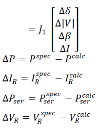 (5) (5) |
| The elements of the various sub matrices are defined as follows |
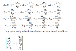 (6) (6) |
III. LOAD FLOW SPECIFICATIONS
|
| The equations in the previous section suggests the use of (Pser,Qser) and (I, β) as control and state variables, respectively, for series devices. The following specifications can be given as per the study to be carried out. |
 |
| This specification is suitable for devices tike TCSC and SSSC, especially if magnitude of , reactive power or reactance required for ensuring a certain current flow in a line. The line flow specification is in terms of current magnitude. Note that the line current magnitude has a direct bearing on losses, line loading, and device limits. This specfication can be considered as the dual of a (Psh,V) specification in conventional load flow. For a vaiable series reactance device like TCSC, the value of the reactance can be obtained from the converged value from the relation. |
 |
| The capability curves of TCSC have a maximum voltage limit on the capacitor. Also in a SSSC, VR is controlled. As such,it is useful to specify Vr as control variable. The jacobian of (5) is used for the load flow solution This specification is dual of (Psh , IR ) specification. |
 |
| Since the MVAr raing is often used as a measure for 5izing of devices, this specification is useful when comparing series devices ratings at different locations. The Jacobian of (eqn 6) is used for the load flow solution. |
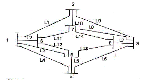
| Formulation presented in the previous section is tested on a sample 8-bus system shown in fig.2. The data for the systems are given in appendix. |
A. Pser-I Specification
|
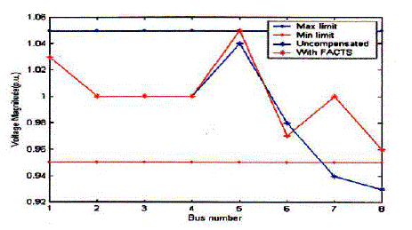
| Since the MVAr raing is often used as a measure for 5izing of devices, this specification is useful when comparing series devices ratings at different locations. The Jacobian of(eqn 6) is used for the load flow solution. In this case an SSSC is connected in line 10 (between bus 2 and 7). The desired line current is 0.5 p.u. The voltage magnitude at the buses across which the device is connected is improved as shown in Fig.3. ln the case of uncompensated system the voltage magnitude at buses 7 and 8 are 0.94 and 0.93 p.u. respectively. But the introduction of FACTS devices, increases the bus voltages to 0.99 and 0.96 p.u respectively. The series FACTS devices injects a series reactive power (Qser) of -0.1441p.u in to the line in which the device is connected. So in order to increase the line current to 0.5 p.u. , the VR reqrired is -0.2882 pu. and the equivalent capacitive reactance of the device is 0.5674 p.u. |
| Also the real power flow through the line in which the device is comected is improved. In the case of uncompensded system the real power flow through the line is 16.59MW but with FACTS device it increases to 18.33 MW. |
B. Pser –Qser Specification
|
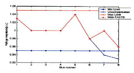
| In this case also an SSSC is connected in line l0 and it injects 4.1 p.u. reactive power. The load flow solution gives a line current of 0.45 p.u.. So the voltage in quadrature with line cnrrent is -0.2222 p.u. and &e equivalent capacitive reactance of the device is 0.4938 p.u. In this case also the voltage magnitude of the buses 7 and 8 are improved as shown in Fig. 4.. The current through the line is improved with FACTS device from 0.4 p.u to 0.45 p.u.. Also the rcal power flow through the line in which the device is connected is improved. In the case of uncompensated system the real power flow fuough the line is l6.59MW but with FACTS device it increases to 17.75 MW. |
V.CONCLUSION
|
| In this paper a dual formulation for load flow studies is presented. It involves use of dual variables and specification for series connected devices in much the same way as for conventional load flow. Also load flow studies with and without FACTS devices are carried out on a sample eight-bus system and the effectiveness of these devices are studied from the load flow results. |
APPENDIX
|
| The data for the sample eight bus system shown in fig.2 is given in table.2 and table 3 below. |
ACKNOWLEDGMENT
|
| We take this opportunity to express our deepest gratitude and appreciation to all those who have helped us directly or indirectly towards the successful completion of this paper. |
Tables at a glance
|
|
|
| |
Figures at a glance
|
 |
 |
 |
 |
| Figure 1 |
Figure 2 |
Figure 3 |
Figure 4 |
|
| |
References
|
- U.P. Mhaskar, A.B.Mote, and A.M.kulkarni, “A New Formulation for Load Flow Solutions of Power Systems with Series FACTSDevices,”IEEE Transactions on Power Systems, Vol.18,No.4
- N.G.Hingaroni and L.Gyugyi, Understanding FACTS:Concept and Technologyof Flexible AC Transmission Systems, New York:IEEEpress2000.
- S. Arabi and P. Kundur, ‘A versatile FACTS device model for power flow md stability simulations," IEEE Transactions on Power Systems,Vol.11,Nov.1996
- C. R. Feurte – Esquivel and E. Acha 'A Newton-type algorithm for the control of power flow in electrical power networks," IEEE Transactionson Power Systems, Vol.12,Nov.1997.
- C- R Fuert-Esquivel, E. Acha, and H.Ambriz-Perez "A Compreheisive Newton-Raphson UPFC Model for the Quadratic Power FowSolutionof Practical Power Networts," IEEProceedings on Generation, Transmission and Distribution, Vol,l5, 1997
- C. R. A. Fuerte-Esquivel, E., "Unified power flow confoller: a critical cornparison of Ncwton-Raphson UPFC algorithms in power flow,studies," IEEProceedings on Generation, Transmission and Distribution, Vol.5, , February 2000..
- Olle I Elgerd, Electic Energy Systems Theory: An Introduction, T.M.H. Edition
- M. Nuoozian and G. Anderson,’Powerr flow control by use of controllable series components," IEEE Transactions on Power Delivery, vol. 8,pp.1420-1429,July 1993.
- D. J. Gotham and G. T. Heydt ‘Power flow control and power flow studies for system with FACTS devices," IEEE Trans. PowerSyst.,vol.13Feb. 1998.
- J. Arriliga and N. R. Watson, Computer modeling of electrical power system, Wiley 2001.
|