ISSN ONLINE(2319-8753)PRINT(2347-6710)
ISSN ONLINE(2319-8753)PRINT(2347-6710)
| Raaja M, Ms.B.Hemamalini and Dr.B.Umamaheshwari Department of Control and Instrumentation Engineering, College of Engineering, Anna University, Chennai, India |
| Related article at Pubmed, Scholar Google |
Visit for more related articles at International Journal of Innovative Research in Science, Engineering and Technology
The Switched Reluctance Motor has inherent mechanical strength without rotor winding and permanent magnet. To improve the power factor correction and to perform the commutation faster, several topologies are analyzed such as buck, boost and buck boost, dc-dc converter. This paper presents the boost converter with PFC to improve the performance of the converter with high rectified output. The proposed converter performs the phase current commutation faster. This paper also presents new controller design for Switched Reluctance Motor. The PI controller is used to track the required line current. The simulation of the SRM along with the Asymmetric Bridge converter and proposed converters are performed by the MATLAB software. The results are analyzed and compared, which shows that the new converter performs the phase current commutation faster than the Asymmetric Bridge converter.
Keywords |
| Switched Reluctance Motor, Boost converter, Power Factor Correction, Commutation, Asymmetric Bridge Rectifier. |
INTRODUCTION |
| The Switched Reluctance Motor is doubly salient and singly excited motor. The SRM becomes more popular because it has some advantages over other motors. The advantages of the SRM are low cost , robustness, reduced size, high fault tolerance, efficiency over wide speed range, production and less volume compared to the other motor drives[1]. The winding is present only on the stator, not on the rotor. The mechanical simplicity of the SRM has some drawbacks. The major drawbacks of the SRM are acoustic noise and the torque ripples. The torque ripples in the SRM are arises, due to the phase current commutation. If the converter has the ability to commutate the phase current faster, then the torque ripples can be reduced. So the converter plays an important role in the Switched Reluctance motor. The converters used for the SRM drives are C dump converter, R dump converter, bifilar, split dc supply and asymmetric bridge converter. The C dump converter is used, because the capacitor in this converter is used to store the energy[2]. The SRMs also offers, some advantages. They can be reliable, since each phase of the SRM is independent of magnetically and electrically from the other motor phases. Very high speeds are also achieved, due to the lack of conductors or magnets on the rotor. |
| The Switched Reluctance Motors are simple machine construction, brushless, fault tolerant, free maintenance and rugged the Switched Reluctance Motors are used in various applications such as washers, dryers, industrial blowers, electrical vehicles, aerospace and centrifugal pumps. |
 |
| The SRM drives are used to reduce the torque ripple, at the higher speeds, but the commutation of the phase current is not so faster[3]. A new control technique is designed to control the SRM at high speeds. The converter used for the SRM drives is for switching the phase currents, this leads to the distorted current waveform. This would results in non unity power factor, for achieving the unity power factor the power factor correction technique is used in Switched Reluctance Motor[4]. |
 |
CONVERTER SELECTION |
| A. Asymmetric Ha lf Bridge Rectifier |
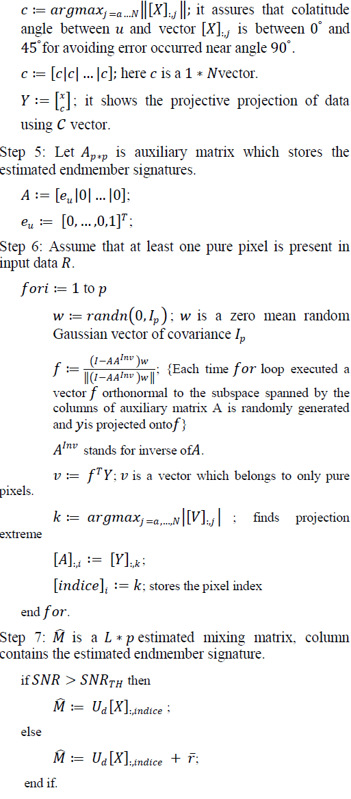
| The most widely used converter for Switched Reluctance Motor is the asymmetric bridge rectifier. In this, the winding is connected between the two switches. Fig.3 shows the asymmetric bridge rectifier, which is most widely used for Switched Reluctance Motor[5]. In this design, each phase winding uses two switches. The switch S2 is in charge of commutation, while the switch S1 is used to perform the PWM switching control. |
 |
| B. A New Proposed SRM Drive Converter |
| The new proposed Switched Reluctance Motor drive topology. The proposed SRM drive looks like a R dump converter and it has higher efficiency than the R dump converter. The proposed converter operates like a C dump converter and it performs phase current commutation faster than the C dump converter. The operation of the proposed converter is very simple and also the phase inductance energy is recovered. |
| The various operating modes of the proposed converter are, |
| i) Magnetization mode |
| ii) Demagnetization mode |
| iii) Overlap of two phases : mode 1 |
| iv) Overlap of two phases : mode 2 |
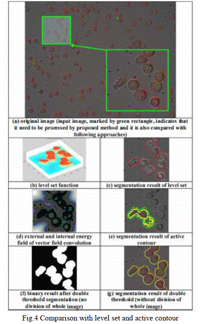 |
| Fig. 6(b) shows the demagnetization mode. The demagnetization mode starts, when the phase current reaches the reference and T1 is turns off. In this mode the diode D1 turns on, Then the voltage across the phase winding is reversed. When the diodes D1 and Db1 turns on, the negative voltage is placed across the phase winding in proportion to coupling ratio which accelerates phase current commutation. |
 |
POWER FACTOR CORRECTION |
| The most widely used power factor correction technique is adding a resistor to a supply side. A sinusoidal reference is needed when converter takes the sinusoidal current from the source. There is some control strategies which force the input current to follow the current reference. The main objective of the power factor correction is to bring the unity power factor closer. The inductive loads are the main cause for the poor power factor, and the poor power factor is corrected by means of adding the capacitors to the circuit. Adding capacitor to the circuit is the simplest technique for correcting the poor power factor. The fixed power factor correction is the capacitor is connected parallel to the device. |
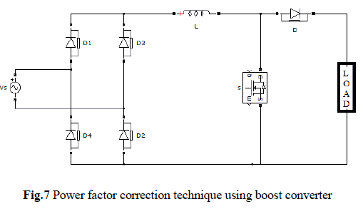 |
| The boost type converters are proposed for improving the characteristics of the converter. The important step is to determine the suitable converter for a given application. For this several methods are considered, such as robustness, power density, efficiency, cost, and complexity. The PFC with the boost converter is the advanced power factor correction technique. It consists of the power factor correction, active power filter and AC-DC converter. A PI control is used for tracking the required line current command. |
| Fig.7 shows the diode rectifier associated with the boost converter which is widely used the in active PFC. The principle behind this is the, combination of the bridge rectifier and a AC-DC converter with filter and the energy storage elements can be extended to the other topologies, such as buck, buck boost and cuk converter. From the topologies said above, boost converter is very simple and it allows the low distorted input currents, with unity power factor using different dedicated control techniques such as the hysteresis, PI control techniques. |
MATLAB/SIMULINK MODELING AND SIMULATION RESULTS |
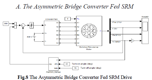
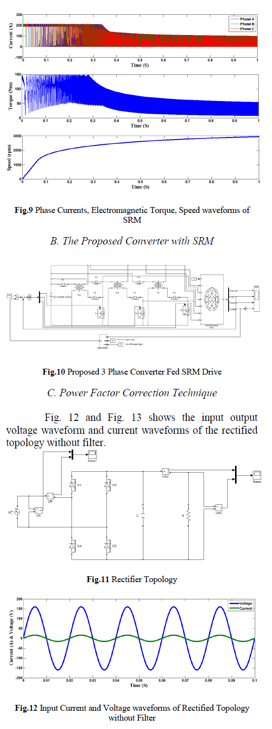
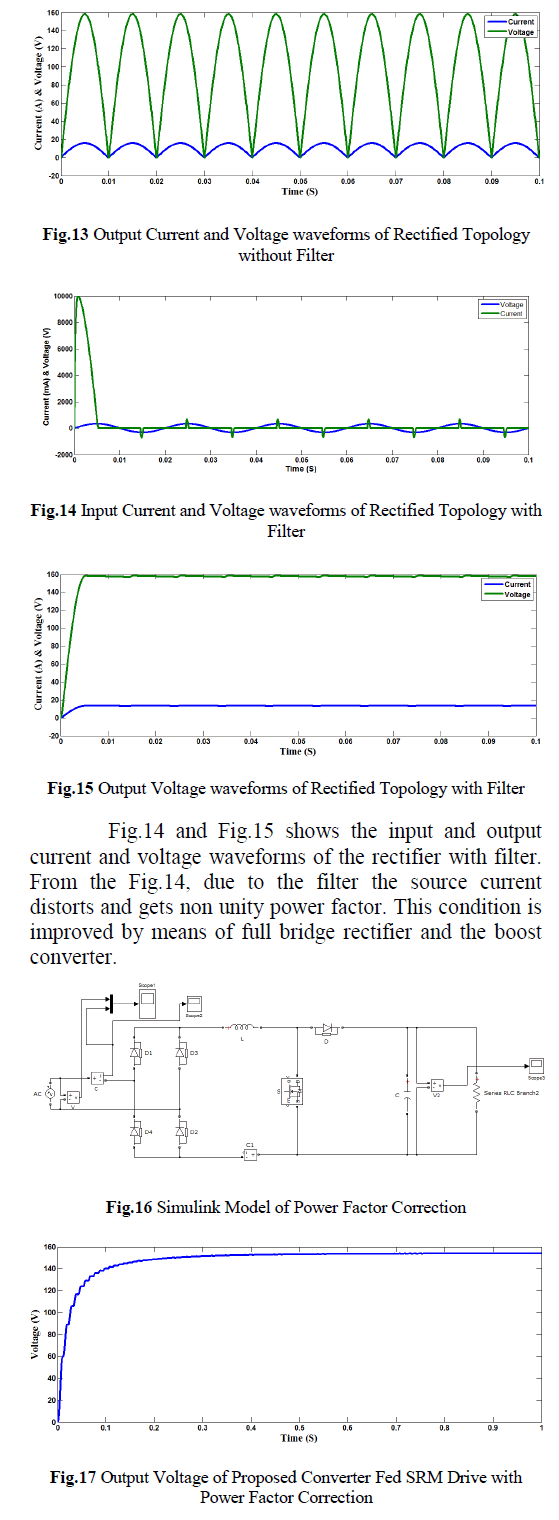
| The simulation is carried out with different cases, the simulation results of the SRM drive with the proposed converter is compared with the results of the Switched Reluctance Motor which uses the asymmetric bridge rectifier and the power factor correction. |
 |
 |
 |
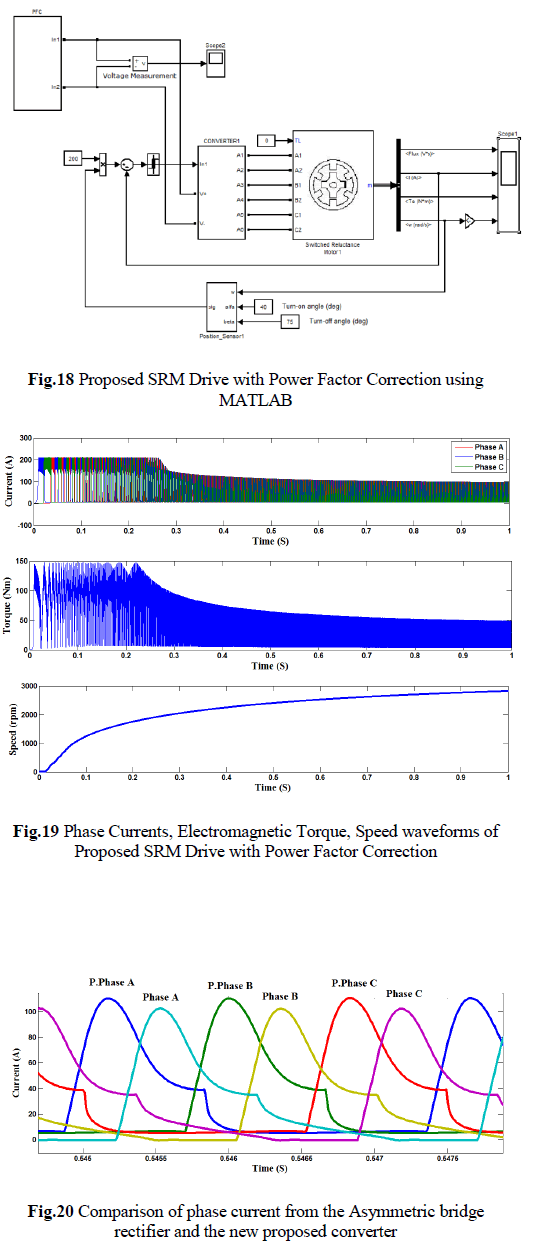 |
| Fig.20 shows phase currents of the Asymmetric bridge rectifier and the proposed converter. From this, the Proposed converter commutates faster than the Asymmetric bridge converter. |
CONCLUSION |
| The power factor correction is achieved by means of boost converter and also a new switched reluctance motor drive is introduced in this paper. The new proposed converter topology for the SRM is analyzed and its various operating modes are discussed. For each motor phase one switch is used in this converter. To achieve a high efficiency, the phase inductance energy is recovered in the proposed converter. In this paper the asymmetric half bridge rectifier and the new proposed converter for the Switched Reluctance Motor drive is analyzed. From this analysis the proposed converter suits better for the Switched Reluctance Motor drive by reducing the number of switches and the power factor correction. The simulation results of both the asymmetric bridge rectifier and new proposed converter fed Switched Reluctance Motor drive is presented in this paper. |
References |
|
 |