Keywords
|
| Clock power reduction, merging, multi-bit flip-flop, replacement, wirelength. |
INTRODUCTION
|
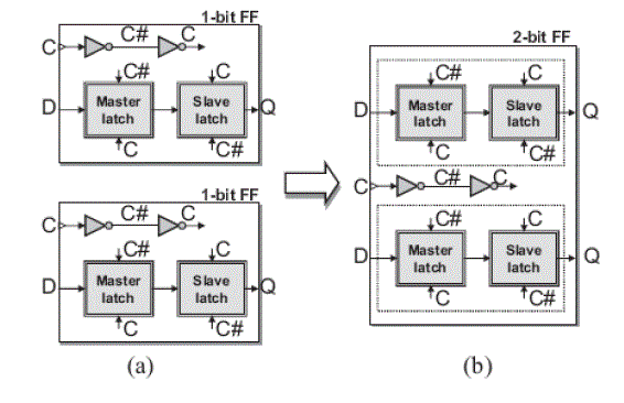
| Due to the popularity of portable electronic products, Low power system has attracted more attention in recent years. Reducing the power consumption not only can enhance battery life but also can avoid the overheating problem, which would increase the difficulty of packaging or cooling. Moreover, in modern VLSI designs, power consumed by clocking has taken a major part of the whole design.. Given a design that the locations of the cells have been determined, the power consumed by clocking can be reduced further by replacing several flip-flops with multi-bit flip-flops. During clock tree synthesis, less number of flip-flops means less number of clock sinks. Thus, the resulting clock network would have smaller power consumption and uses less routing resource. Besides, once more smaller flip-flops are replaced by larger multi-bit flip-flops; device variations in the corresponding circuit can be effectively reduced. Fig. 1 shows the clock diagrams of 1- and 2-bit flip-flops. If we replace the two 1-bit flip-flops as shown in Fig. 1(a) by the 2-bit flip-flop as shown in Fig. 1(b), the total power consumption can be reduced because the two 1-bit flip-flops can share the same clock buffer. However, the locations of some flip-flops would be changed after this replacement, and thus the wirelengths of nets connecting pins to a flip-flop are also changed. To avoid violating the timing constraints, we restrict that the wirelengths of nets connecting pins to a flip-flop cannot be longer than specified values after this process. Besides, to guarantee that a new flipflop can be placed within the desired region, we also need to be considering the area capacity of the region. Given a design that the locations of the cells have been determined, the power consumed by clocking can be reduced further by replacing several flip-flops with multi-bit flip-flops. During clock tree synthesis, less number of flip-flops means less number of clock sinks. Thus, the resulting clock network would have smaller power consumption and uses less routing resource. |
RELATED WORK
|
| They use the graph-based approach. In a graph, each node represents a flip-flop. If two flip-flops can be replaced by a new flip-flop without violating timing and capacity constraints, they build an edge between the corresponding nodes. After the graph is built, the problem of replacement of flip-flops can be solved by finding an m-clique in the graph. The flip-flops corresponding to the nodes in an m-clique can be replaced by an m-bit flip- flop. They use the branch-and-bound and backtracking algorithm to find all m-cliques in a graph. Because one node (flip-flop) may belong to several m-cliques (m-bit flip-flop), they use greedy heuristic algorithm to find the maximum independent set of cliques, which every node only belongs to one clique, while finding m-cliques groups. However, if some nodes correspond to k-bit flip-flops that k 1, the bit width summation of flip-flops correspond- ing to nodes in an m-clique, j , may not equal m. If the type of a j -bit flip-flop is not supported by the library, it may be time-wasting in finding impossible combinations of flip -flops. |
OUR CONTRIBUTIONS
|
| The difficulty of this problem has been illustrated in the above descriptions. To deal with this problem, the direct way is to repeatedly search a set of flip-flops that can be replaced by a new multi-bit flip-flop until none can be done. However, as the number of flip-flops in a chip increases dramatically, the complexity would increase exponentially, which makes the method impractical. To handle this problem more efficiently and get better results, we have used the following approaches. |
| 1) To facilitate the identification of mergeable flip-flops, we transform the coordinate system of cells. In this way, the memory used to record the feasible placement region can also be reduced. |
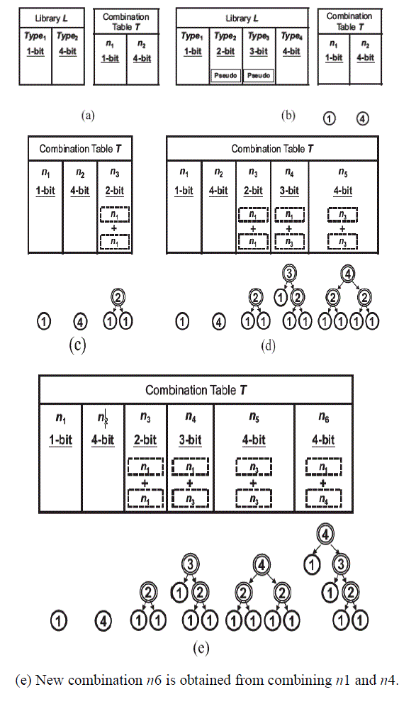
| 2) To avoid wasting time in finding impossible combinations of flip-flops, we first build a combination table before actually merging two flip-flops. For example, if a library only provides three kinds of flip-flops, which are 1-, 2-, and 3-bit, we first separate the flip-flops into three groups. Therefore, the combination of 1- and 3-bit flip-flops is not considered since the library does not provide the type of 4-bit flip-flop. |
| 3) We partition a chip into several sub regions and perform replacement in each sub region to reduce the complexity. However, this method may degrade the solution quality. To resolve the problem, we also use a hierarchical way to enhance the result. |
PROPOSED METHOD
|
DESIGN FLOW
|
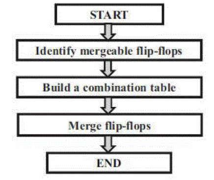
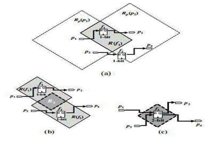
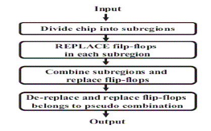
| Our design flow can be roughly divided into three stages .In the beginning, we have to identify a legal placement region for each flip-flop fi .First, the feasible placement region of a flip-flop associated with different pins are found based on the timing constraints defined on the pins. Then, the legal placement region of the flip-flop fi can be obtained by the overlapped area of these regions. However, because these regions are in the diamond shape, it is not easy to identify the overlapped area .Therefore, the overlapped area can be identified more easily if we can transform the coordinate system of cells to get rectangular regions. In the second stage, we would like to build a combination table, which defines all possible combinations of flip-flops in order to get a new multi-bit flip-flop provided by the library. |
| The flip-flops can be merged with the help of the table. After the legal placement regions of flip-flops are found and the combination table is built, we can use them to merge flip-flops. To speed up our program, we will divide a chip into several bins and merge flip-flops in a local bin. However, the flip-flops in different bins may be mergeable. Thus, we have to combine several bins into a larger bin and repeat this step until no flip-flop can be merged anymore. |
BUILD A COMBINATION TABLE
|
| we may add pseudo types, which denote those flip-flops that are not provided by the library, For example, assume that a library only supports two kinds of flip-flops whose bit widths are 1and 4, respectively. In order to use a binary tree to denote a combination whose bit width is 4, there must exist flip-flops whose bit widths are 2 and 3. |
| Let bmax and bmin denote the maximum and minimum bit width of flip-flops in L. In InsertPseudoType, it inserts all flipflops whose bit widths are larger than bmin and smaller than bmax into L if they are not provided by L originally. After this procedure, all combinations in L are sorted according to their bit widths in the ascending order. At present, all combinations are represented by binary trees with 0-level. Thus, we would assign NULL to its right and left child. Finally, for every two kinds of combinations in T, we try to combine them to create a new combination. If the new combination is the flip-flop of a feasible type (this can be checked by the function Type Verify), we would add it to the table T. In the function Type Verify, we first add the bit widths of the two combinations together and store the result in bsum. Then, we will add a new combination n to T with bit width bsum if L has such kind of a flip-flop. After these procedures, there may exist some duplicated or unused combinations in T. Thus, we have to delete them from the table and the two functions Duplicate Combination Delete and Unused Combination Delete are called for the purpose In DuplicateCombinationDelete, it checks whether the duplicated combinations exist or not. If the duplicated combinations exist, only the one with the smallest height of its corresponding binary tree is left and the others are deleted. In Unused Combination Delete, it checks the combinations whose corresponding type is pseudo in L. If the combination is not included into any other combinations, it will be deleted. |
MERGE FLIP-FLOPS
|
| In merging of flip flops to reduce the complexity, we first divide the whole placement region into several subregions, and use the combination table to replace flip-flops in each subregion. Then, several subregions are combined into a larger subregion and the flip-flops are replaced again so that those flip-flops in the neighboring subregions can be replaced further. Finally, those flip-flops with pseudo types are deleted in the last stage because they are not provided by the library. |
| Region Partition |
| To speed up our problem, we divide the whole chip into several subregions. By suitable partition, the computation complexity of merging flip-flops can be reduced significantly we divide the region into several subregion, each subregion contains sixbins.bin is a small unit of subregion. |
SIMULATION RESULTS
|
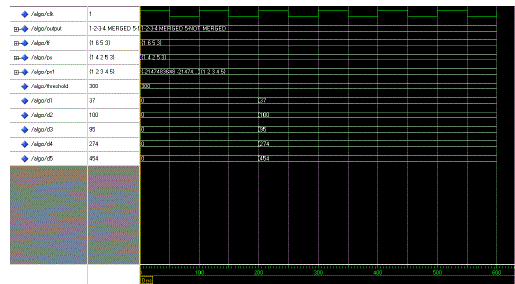
| Flip flop Merging output |
 |
| Proposed Power |
 |
| Existing Power |
 |
CONCLUSION
|
| This paper has proposed an algorithm for flip-flop replacement for power reduction in digital integrated circuit design. The procedure of flip-flop replacements is depending on the combination table, which records the relationships among the flip -flop types. The concept of pseudo type is, introduced to help to enumerate all possible combinations in the combination table. By the guidelines of replacements from the combination table, the impossible combinations of flip-flops will not be considered that decreases execution time. Besides power reduction, the objective of minimizing the total wirelength also is considered to the cost function. The experimental results show that our algorithm can achieve a balance between power reduction and wirelength reduction. |
Figures at a glance
|
 |
 |
 |
 |
 |
| Figure 1 |
Figure 2 |
Figure 3 |
Figure 4 |
Figure 5 |
|
| |
References
|
- P. Gronowski, W. J. Bowhill, R. P. Preston, M. K. Gowan, and R. L.Allmon, “High-performance microprocessor design,” IEEE J. Solid-StateCircuits, vol. 33, , May 1998.
- D. Duarte, V. Narayanan, and M. J. Irwin, “Impact of technology scaling in the clock power,” in Proc. IEEE VLSI Comput. Soc. Annu. Symp.,Pittsburgh, PA, Apr. 2002, pp. 52–57.
- H. Kawagachi and T. Sakurai, “A reduced clock-swing flip-flop (RCSFF) for 63% clock power reduction,” in VLSI Circuits Dig. Tech. PapersSymp.,Jun. 1997, pp. 97–98.
- Y. Cheon, P.-H. Ho, A. B. Kahng, S. Reda, and Q. Wang, “Power-aware placement,” in Proc. Design Autom. Conf., Jun. 2005, pp. 795–800.
- Y.-T. Chang, C.-C. Hsu, P.-H. Lin, Y.-W. Tsai, and S.-F. Chen,“Post-placement power optimization with multi-bit flip-flops,” in Proc.IEEE/ACM Comput.-Aided Design Int. Conf., San Jose, CA, Nov. 201pp. 218–223.
|