Keywords
|
| Artificial Neural Network, Backpropogation Algorithm, Fourier Transform, Wavelet Transform . |
INTRODUCTION
|
| Electricity is the most revolutionary development in the human history. The contribution of electric energy in day-today affairs is immense. Industrialisation has led to a current scenario that, no electricity means no useful output. And all emerging technologies rely upon an electric supply. Virtually it can be said that all equipments depend upon electrical energy in one form or the another. With the advent of new technologies the equipments that are in use is increasing daily. More sensitive electronic equipments have led to another technological failure- depletion of power quality. Power quality disturbances deforms the purity of an electric signal and moreover it results in failures to other sensitive equipments in the system. Power quality disturbance ranges from fast and furious transients to short and long outages. They include noisy flickers to momentary sags and swells. Repeated occurance of sags and swells can result in damage of electronic equipments. In some cases it can pose harm to the equipment performance and its reliability. These power quality disturbances are unpredictable and hence their identification as soon as they occur in a system defines the efficiency and stability of a transmission and distribution system. Here comes the need for an automatic, fast and easy method of power quality assessment. |
| Power monitors are available at various nodes along a transmission system with diversified functionalities, to gather and store electrical events and conditions involved. But they are not intelligent enough to identify and classify the power quality disturbance occurring in a system. This again justifies the need for a fully automatic and intelligent offline method for power quality disturbance classification. |
| During signal analysis, to identify between various disturbance conditions certain efficient features should be defined. Efficient features which aids in better classification of power quality disturbance are identified, later these are used for training an artificial neural network. Three level testing is done to check the efficieny and applicability of the method for power quality classification. The potential of this method can be well clarified by extending the method for fault classification and faulty phase identification in a prototype system. |
MATHEMATICAL TRANSFORMS USED FOR FEATURE EXTRACTION
|
| The most critical stage of any signal processing or pattern recognition is the extraction of distinctive features from th raw data. The characteristics should be chosen such that they have very low computational time and distinct features to separate the various disturbances. Signal processing deals with the extraction of the typical informations from the raw signal. A number of signal processing tools have been developed which leads to easy and efficient classification of various disturbance events within a signal. Fourier Transform, Wavelet Transform, Short time Fourier Transform, Chirp Z Transform, HilbertâÃâ¬ÃŸs transform etc. are some of them. |
| Most of the signals are of Non-stationary nature, so most of the informations cannot be collected from its time domain. The eavaluation of their frequency characteristics is of atmost importance. This calls out for the need of advance transforms. Here wavelet transform and fourier transform is used in unison for extracting typical and efficient features from the raw signal. |
| A. Fourier Transforms |
| Fourier Transform or Fourier based techniques are undoubtedly the unheralded workhorse in engineering. It is used practically in every fields of engineering including power engineering. Although new techniques are constantly being developed and proposed, Fourier still dominates in real-world application. One possible reason for its continuing dominance is perhaps familiarity but it is equally valid to stress that Fourier techniques are still deemed adequate for most practical applications. Fourier Transform enables us to view phenomenon in the frequency domain instead of the usual time domain. A waveform is broken down into a series of sinusoids, each with its own magnitude, phase shift and frequency. |
| The original waveform is the superposition of all these sinusoids. It is particularly useful if ones wish to discover specific frequency components. It is most widely used in harmonic analysis of periodic waveform, but is also applied to oscillatory transient to identify the dominant frequency.Proponents of new techniques such as Wavelets tend to brag that FourierâÃâ¬ÃŸs assumes the analyzed waveform to be periodic and hence, is not suitable for transients. The transform window length needs to be long so as to achieve sufficient frequency resolution. Otherwise, spectral leakage would occur resulting in erroneous results. However, the measurement requirements also need to be taken into consideration. For oscillatory transient, an error of several Hz would still be acceptable since the oscillatory frequency is in the order of hundredth of Hz or kHz. |
| In addition, it is often derided as applicable to stationary signal only. Windowing such as used in Short Time Fourier Transform concentrates the energy of Fourier spectrum at a certain point in time, preserving the time information. This has enabled signal with multiple varying harmonic components to be readily studied in the frequency domain. With these complementary pre-processing, it is indisputable that Fourier Transform will still be the main method for many more years. |
| Fourier transform enables us to view phenomenon in the frequency domain instead of the usual time domain. Here, a waveform is broken down into a series of sinusoids, each with its own magnitude, phase shift and frequency. The original waveform is the superposition of all these sinusoids. It is particularly useful if one wish to discover specific frequency components. |
| The Discrete Fourier Transform of the input signal x (n) is given by, |
 |
| where X(k) is the discrete Fourier transform at the frequency .k , N is the window length, .k=2k ωk/N is set of fixed and equally spaced frequencies, 0 ≤ k ≤ N-1. |
| B. Wavelet Transforms |
| Wavelets Transform has taken the information engineering by storm over the past two decades. Its main forte is its ability to retain the time information while expanding a signal onto the frequency domain. It achieves this by correlating the signal with a scaled and shifted version of a basis called mother wavelet Firstly, there are several schemes for implementing Wavelets Transform. CWT (Continuous Wavelet Transform) computes the coefficients for all scales and time translations. DWT (Discrete Wavelet Transform) on the other hand only transforms into several frequency bands with more emphasis (better frequency resolution) at the low frequencies than at the high frequencies. It is argued that frequency precision is more important at low frequencies than at high frequencies. Another scheme, Wavelets Packet is similar to DWT except that equal emphases are given to both low and high frequency components, i.e. similar frequency resolution across the entire frequency range. The second strength of Wavelet Transform is the freedom of choice in its basis function (appropriately called as mother wavelet,). Unlike FourierâÃâ¬ÃŸs, whose basis is fixed for sinusoidal functions, there is a wide range of mother wavelets to choose. Normally, a mother wavelet that resembles the analyzed signal is the best choice as this would reduce the number of non-zero Wavelets coefficients. Wavelet decomposition enables multiresolution analysis as a single signal can be broken down into multiple frequency bands. |
| Wavelet transformation has the ability to analyse disturbance waveform simultaneously in both time and frequency domains[1]. The wavelet transform is useful in detecting and extracting disturbance features of various types of electric power quality disturbances because it is sensitive to signal irregularities but insensitive to the regular-like signal behavior . |
| Wavelet analysis expands functions not in terms of trigonometric polynomials but in terms of wavelets, which are generated in the form of translations and dilations of a fixed function called the mother wavelet. A mother wavelet is a function that oscillates, has finite energy and zero mean value. Normally, the mother wavelet that resembles the analyzed signal is the best choice, as this would reduce the number of non-zero Wavelet coefficients. Wavelet theory is expressed by continuous wavelet transformation as |
 |
| As time information is preserved, Wavelet transform is popular for transient signal analysis. It performs exceedingly well in pinpointing discontinuities in a signal. Hence, it is commonly used for locating the starting and ending points of a disturbance. In power quality problems analysis, discrete wavelet transformation is adequate to classify the power quality problems. |
| The WT is a relatively new processing tool, which performs time localization of different frequency components of a given signal. Therefore, by using WT, both time and frequency resolution of a given signal is accomplished. WT performs this task by using some unique analyzing functions, called mother wavelets. The unique property of the mother wavelets is that for high-frequency components, the time intervals would be short whereas for low frequency components, the time intervals would be longer. Thus, WT is a quite useful technique for characterizing the transient signals occurring in a power system, and a result, in recent times, many applications of WT for analyzing the power system transient signals have been reported in the literature. There are different types of mother wavelets available in the literature, such as Harr, Daubechies (db), Coiflet(coif), symmlet (sym), etc. The choice of the mother wavelet plays a major role in the characterization of the signal under study. The mother wavelet, whose characteristics matches closely with the signal under consideration, would be the best choice. |
| For studying power system fault signals, it has been reported in the literature that db wavelet is the most suitable one Therefore, in this paper also, db wavelets have been used for the first stage analysis of the fault current . |
| In discrete wavelet transform, In the first stage, the original signal is decomposed into two halves of frequency components by using high-pass filter (HPF and low-pass filter (LPF). In the second stage, the output of the LPF is sent again to another set of HPF and LPF to further decompose the signal into two halves of frequency components. This process is repeated till the desired level of decomposition of the original signal is achieved. If the sampling frequency of the original signal is fs then following the sampling theorem, the highest frequency component that the signal could contain is fs/2 . |
| Hence, in the first level, the band of frequencies between fs/2 and fs/4 would be captured. In the second level, the band of frequencies between fs/4 and fs/8 would be captured and so on |
PROCEDURE FOR POWER QUALITY DISTURBANCE CLASSIFICATION
|
| A. Power Quality Sample Creation |
| Artificial neural network training requires as many as training data to increase its efficiency. Here the input to ANN is the features extracted from the power quality signal samples. So the first step in the entire procedure starts with sample creation. Power quality disturbance signals can be created by making conceptual changes in the equation of a purely sinusoidal signal. For example: sag is a decrease in magnitude within .1 to.8 pu, for a particular time period. This signal can be created by making required modification in the equation for a pure sinusoidal signal. And by varying the range between .1 to .8 (controlling range) as many samples can be created. |
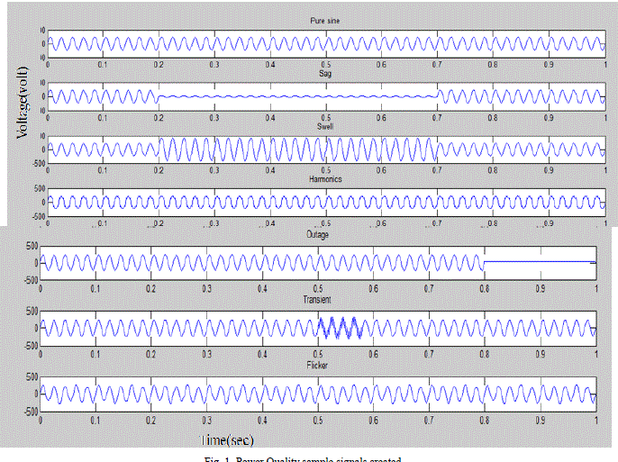
| Six power quality disturbances were considered for classification namely sag,swell,transient,outage ,flicker,and harmonics.Table 1 shows the modified equations for each of the power quality disturbances based on their standard definitions. Figure 1 shows a single sample of all the 6 power quality events. |
| B. Feature Identification |
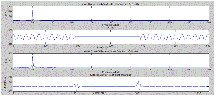
| The efficiency of any classification problem depends upon the uniqueness and accuracy of features used for classification[7]. Mathematical Transforms are commonly used for feature identification. Fourier transform, Wavelet transform,S-transform etc. can be used for feature extraction.initially used transform was fourier transform. But wavelet transform is extremely efficient in pinpointing the time of occurance of a disturbance. In this paper the advantages of both these transforms are incorporated. Fourier transform and Wavelet transform is used combinedly to extract typical features from the disturbance signal samples. Mother wavelet used is Daubechius 8(Db8). The fourier and wavelet spectrum of each of the disturbance signal samples is plotted in a graph. Figure 2 shows the fourier and wavelet spectrum of disturbance „outageâÃâ¬ÃŸ. |
| Extremely efficient and typical 5 features are chosen. Two features are based on wavelet transforms, they are peak of the second level detail and energy level of the second level detail wavelet coefficient respectively. Three features are extracted applying fourier transform to the disturbance signal. |
| The five features used for detecting the power quality issues are described below: |
| 1) Energy of the Second level Detailed wavelet coefficient. |
 |
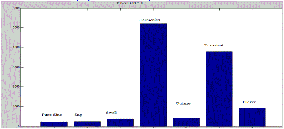
| WC is the second level detailed wavelet coefficient. The mother wavelet used is Daubechius 8. This feature represents the summation of the absolute value of all the second level detailed wavelet coefficients. The average values of this feature for all the power quality disturbance event as well as purely sinusoidal signal is plotted . The bar graph in figure 3 shows that each of the events are having peculiar values for this feature. From this it is clear that this wavelet based feature is extremely efficient in distinguishing between various power quality disturbances. |
| 2) Peak of the wavelet coefficients |
 |
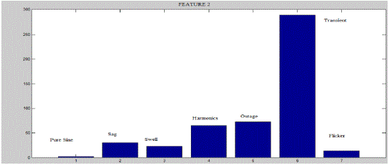
| Second feature is the maximum or peak value of the wavelt coefficient of the particular signal under consideration. As discussed earlier wavelet transform has a typical ability to pinpoint the starting point of a disturbance. Wavelet details will have a peak value for the starting and ending of a disturbance, but it also have a peak value for starting and ending point of a signal. So before employing this feature equation the start and end point values are discarded or else it can lead to misleading feature values. Figure 4 shows the graph depicting that average value of this feature for each of the disturbance events are typical. |
| 3)Difference between Fundamental and Test signal |
 |
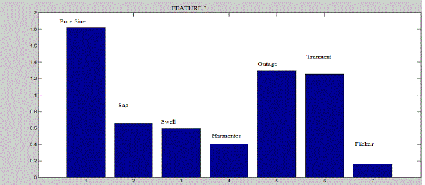
| Third feature is based on Fourier transform. The difference between the discrete Fourier transform of the test signal and the DFT of the fundamental signal is the third feature. Here V is the test signal which represents the power quality disturbance signals and Vf is the DFT of the fundamental signal that is the pure sinusoidal signal without any power quality disturbance incorporated. Figure 5 shows the graph depicting average value of this feature for various disturbances |
| 4)Difference between Phase angle shift of Fundamental and Test signal |
 |
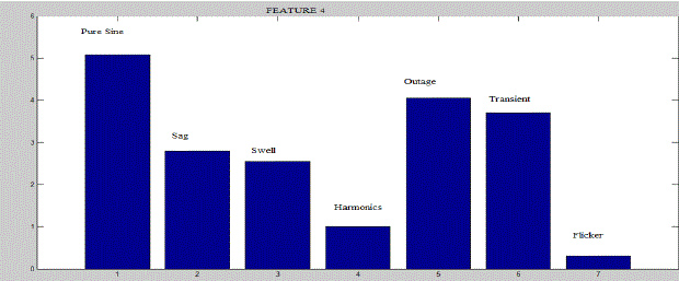
| Fourth feature is also based on Fourier transform. The difference between the phase angle shift of the test signal and phase angle shift of the fundamental signal is the fourth feature. Here V is the DFT of the test signal which represents the power quality disturbance signals and Vf is the DFT of the fundamental signal. Figure 6 shows the graph depicting average value of this feature for various disturbances. |
| 5)Difference in RMS value between Fundamental and Test signal |
 |
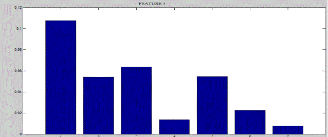
| Fifth feature is also based on Fourier transform. The difference between the Root mean squared value of the test signal and phase angle shift of the fundamental signal is the fifth feature. Here V is the DFT of the test signal which represents the power quality disturbance signals and Vf is the DFT of the fundamental signal. Figure 7 shows the graph depicting average value of this feature for various disturbances as well as pure sine signal. |
| All these 5 features are having typical values for the various power quality disturbances. |
| C. Neural Network as a Classifier |
| Feedforward neural network with Backpropagation algorithm is used as neural classifier[5].The developed ANN model has an input layer with 5 nodes. The 5 input neurons are fed with the 5 features extracted before for each of the disturbance samples. The hidden layer has 50 nodes and the output layer has 1 nodes representing the various disturbances voltage sag, swell, harmonics, transient, outage, flicker and puresine (fundamental) as { 1 2 3 4 5 6 7 } The inputs for training ANN are the five features extracted as mentioned in the previous section. The training is set with learning rate 1e-006, maximum epochs 5000 and target error 0.0001. After training of the ANN, the weight and bias can be used to detect the power quality problems. The randomly selected 100 signals from each power quality event is used to test the ANN. |
| D. Power Quality Classification System:Testing |
| Once the system for power quality disturbance classification is made it is very essential to test whether the system is capable of detecting the disturbances correctly. A three level testing is done for instance. First the system efficiency was tested by evaluating the power quality disturbances present in the samples used for training the neural network. The system could efficiently classify the type of power quality disturbance in present in each of the samples. This was the first level testing. The simulation result for this is shown in the table 2 below. |
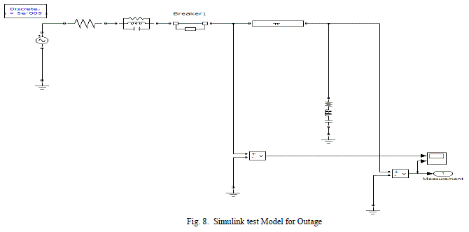
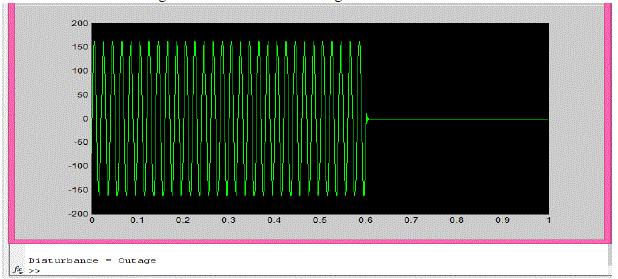
| Simulink models incorporating various power quality disturbances was created with the help of breaker operations. The signal from the model was extracted and while running the program, it efficiently detected the type of power quality disturbance that was present in the system. This is the second level testing. The simulink model created for an outage is shown in figure 8. |
| Model parameters: |
| Source voltage: 230v, 50hz |
| Parallel RLC branch: R=1 ohm,L=1e-3H,C=1e-6F |
| Transmission line: length:100km |
| Resistance/km: .2568 ohm |
| Inductance/km : 2e-3H/km |
| Capacitance/km : 8.6e-9F/km |
| Breaker operation: closed- .6 seconds |
| While running the program for identification of power quality disturbance in this particulat transmission line model, it accurately classified the power quality disturbance as outage. This is depcted in the fihure 9. Figure 9 shows the output waveform after simulating the simulink model of outage. |
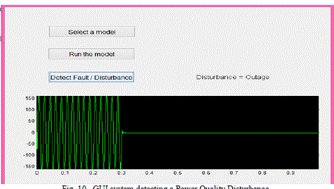
| A Graphical user Interface (GUI) was created to make the classification more user friendly. A GUI system helps in a user friendly detection of the type of power quality disturbance present within the test model. |
| The GUI test sytem classifying a power quality disturbance is shown in figure 10. |
CONCLUSION
|
| A very strong method for classifying power quality disturbances is the main objective fulfilled in the paper. The practicability of this method is tested by implementing the method in a real time system. The method has immense potentials like, it can be extended to detect the faults in a transmission system as well as faulty phase at which a particular fault has occurred. It can be used for detecting and even predicting the fault currents that can occur in a transmission line |
| The system could efficiently classify the power quality disturbances with an efficiency about 99.4%. The required efficiency goal is obtained within 281 epochs. |
Tables at a glance
|
 |
 |
| Table 1 |
Table 2 |
|
Figures at a glance
|
 |
 |
 |
 |
 |
| Figure 1 |
Figure 2 |
Figure 3 |
Figure 4 |
Figure 5 |
 |
 |
 |
 |
 |
| Figure 6 |
Figure 7 |
Figure 8 |
Figure 9 |
Figure 10 |
|
References
|
- D T Ngyuen , A Hoang “Analysis of power transient disturbances using wavelet transform technique” IEEE Transactions on Power Systems,vol.7, no. 1, pp. 54-64,February 2001.
- W. Kanitpanyacharoean and S. Premrudeepreechacharn, “ Power Quality Problem Classificatrion using wavelet Transformation and ArtificialNeural networks”IEEE Region 10 conference, vol C, Nov2004, pp. 252-255.
- Dolores Borras, M. Castilla, Narciso Moreno and J.C.Monatafio,”wavelet and Neural Structure: A new Tool for Diagnostic of Power systemDisturbances”, IEEE Transaction on Industrial Applications, vol37, No.1, January 2001. pp. 445-463.
- T.K. Abdel-Galil, M. Kamel, A.M. Youssef, E.F.El-Saadany and M.M.A. Salama,”Power Quality Disturbance Classification using the InductiveInterference Approach”, IEEE Transactions on Power Delivery, vol9,No.4,Octiber 2004. pp. 1034-1043.
- M.Negnevitsky Discussion of “Power Quality Disturbance Waveform Recognition Using Wavelet-Based Neural Classifier-Part 1: TheoreticalFoundation”, IEEE Transactions on Power Delivery, Vol. 15, No. 4, October 200, pp.544 – 551.
- C.-H. Lin and M.-C. Tsao “Power Quality detection withclassification enhancible wavelet-probabilistic network in a power system” IEE Proc.-Gener. Transm.Distrib. Vol 152,No.6,Nov 2005,pp.223-230
- S. Chen, “ Feature Selection for Identification and classification of Power Quality Disturbances”, IEEE Power Engineering Society GeneralMeeting , Issue 12-16, June 2005 , pp.2301-2306.
|