Keywords
|
| Brushless dc motor (BLDCM), Cuk converter, Diode Bridge Rectifier (DBR), Power factor correction (PFC), voltage-source inverter (VSI). |
INTRODUCTION
|
| Brushless Direct Current (BLDC) motors are one of the motor types rapidly gaining popularity. BLDC motors are used in industries such as Appliances, Automotive, Aerospace, Consumer, Medical, Industrial Automation Equipment and Instrumentation. As the name implies, BLDC motors do not use brushes for commutation; instead, they are electronically commutated. BLDC motors have many advantages over brushed DC motors and induction motors. A few of these are: |
| • Better speed versus torque characteristics |
| • High dynamic response |
| • High efficiency |
| • Long operating life |
| • Noiseless operation |
| • Higher speed ranges |
| In addition, the ratio of torque delivered to the size of the motor is higher, making it useful in applications where space and weight are critical factors. The commutation in a PMBLDCM is accomplished by solid state switches of a three-phase voltagesource inverter (VSI)[1]. |
| A typical motor drive consists of a rectifier, dc link, and an inverter as shown in fig.1. A large electrolytic capacitor is usually installed in dc link to stabilize the dc voltage[2]. |
| This motor drive draws a pulsed current from ac mains because of the uncontrolled charging of dc link capacitor. However, it draws a large current when the ac voltage is higher than the dc link voltage. Therefore, many power quality (PQ) problems arise at input ac mains and they are undesirable. There are many means explored and proposed to solve this severe problem. Power factor correction method is a good candidate for ac to dc power conversion in order to reduce the line current harmonics as well as increase the efficiency and capacity of motor drives. The use of power factor correction topologies is, therefore, mostly recommended for such drives[3]. |
| The dc-dc converters, which act as PFC converters, forces the drive to draw sinusoidal ac mains current in phase with its voltage[4]. In this paper a Cuk dc–dc converter is used as a PFC converter because of its continuous input and output currents, small output filter, and wide output voltage range as compared to other single switch converters. A three-phase voltage-source inverter is used as an electronic commutator to operate the PMBLDCM. |
CUK CONVERTER FED PMBLDC MOTOR
|
| Fig.2 shows the block diagram for power factor corrected BLDC motor drive. To generate switching sequence for the VSI feeding the PMBLDC motor, the rotor position signals are taken by Hall-effect sensors and therefore, rotor position is required only at the commutation points. |
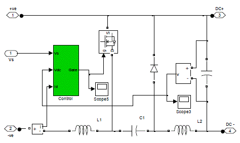
| The Cuk dc–dc converter controls the dc link voltage using capacitive energy transfer. In this topology, a conventional DBR is fed from single-phase ac mains. Its output is given to a DC-DC converter, and a VSI is used to feed the PMBLDC motor. The DC-DC converter provides a controlled dc voltage from uncontrolled dc output of DBR, while controlling the power factor through high frequency switching of the PFC switch. |
| A. Design and Matlab model Of Cuk PFC Converter For PMBLDCM |
| The Cuk PFC converter is designed for a PMBLDCM drive having DBR at front end, on the basis of PQ constraints at ac mains and allowable ripple in dc-link voltage. The output voltage (Vdc) of the Cuk PFC converter is given as, |
 |
| Where, Vin is the average value of the output DC voltage from a DBR, derived from an ac input voltage (Vs) as, |
 |
| The values of boost inductor and capacitor used in cuk converter for energy transfer is given by, |
 |
 |
| where ΔIL1 is the inductor current ripple, ΔVC1 is the voltage ripple in the intermediate capacitor (C1), and Idc is the current drawn by the PMBLDCM from the dc link. |
| For ripple-free voltage at the dc link of the Cuk converter a ripple filter is designed. For a given switching frequency (fs), the inductance (L2) of the ripple filter restricts the inductor peak-to-peak ripple current (ΔIL2) within a specified value. The capacitance (C2) is calculated for the allowed ripple in the dc link voltage (ΔVC2)[5],[6]. The values of the ripple filter inductor and capacitor are given as, |
 |
 |
| Fig.3 shows the matlab model of Cuk Converter, which is used as a power factor correction converter for PMBLDC motor drive. |
MATHEMATICAL MODELLING OF PMBLDC MOTOR DRIVE
|
| The modelling of PMBLDCM drive involves modelling of the PFC converter and PMBLDCM drive. These components are modelled in the form of mathematical equations and the complete drive is represented as a combination of these models. |
| A. PFC Converter |
| The PFC converter consists of a DBR at front end and a Cuk converter with an output ripple filter. The PFC converter modelling consists of the modelling of a speed controller, a reference current generator, and a PWM controller as given below. |
| 1) Speed Controller: The Speed Controller is a PI controller which closely monitors the speed error as an equivalent voltage error and generates control signal (Ic) to minimize the error. If at kth instant of time, V* dc(k) is reference DC link voltage, Vdc(k) is sensed dc link voltage then the voltage error Ve(k) is calculated as, |
 |
| The output of the controller Ic(k) at kth instant is given as, |
 |
| Where, Kpv and Kiv are the proportional and integral gains of the voltage PI controller. |
| 2) Reference Current Generator: The reference current at the input of the Cuk converter is, |
 |
| where ud is the unit template of the ac mains voltage, calculated as, |
 |
| 3) PWM Controller: The reference input current of the Cuk converter (i*d) is compared with its current (id) sensed after DBR to generate the current error Δi. This current error is amplified by gain kd and compared with fixed frequency (fs) sawtooth carrier waveform md(t) to get the switching signal for the MOSFET of the Cuk converter as, |
 |
| where S denotes the switching of the MOSFET of the Cuk converter representing „ONâÃâ¬ÃŸ position with S=1 and its „OFFâÃâ¬ÃŸ position with S=0. |
| B. The PMBLDC Motor Drive |
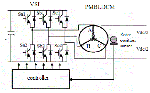
| The PMBLDCM drive has an electronic commutator, a voltage source inverter and a PMBLDC motor as the main components. |
| 1) Electronic Commutator: The Electronic commutator uses signals from Hall-effect position sensors to generate the switching sequence for the VSI. |
| 2) Voltage Source Inverter: Fig.4 shows the PMBLDC Motor Drive system. |
| The output of VSI to be fed to phase „AâÃâ¬ÃŸ of the PMBLDC motor is given as, |
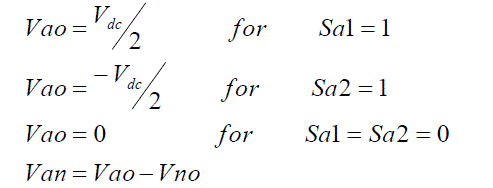 |
| Where Vao, and Vno are voltages of phase A and neutral terminal with respect to virtual mid-point of the dc link. Using similar logic Vbo, Vco, Vbn, Vcn are generated for other two phases of the VSI feeding PMBLDC motor. The voltages Van, Vbn, and Vcn are voltages of three-phases with respect to the motor neutral terminal (n). |
| 3) PMBLDC Motor: The PMBLDCM is represented in the form of a set of differential equations given as, |
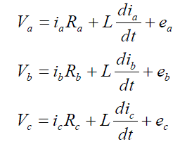 |
| In these equations, ia, ib, and ic are currents, and ea, eb, and ec are the back EMFs of PMBLDCM, in respective phases; R is the resistance of motor windings/phase and L is the inductance. The developed torque Te in the PMBLDCM is given as, |
 |
| where ω is the motor speed in radians per second. Since PMBLDCM has no neutral connection, |
 |
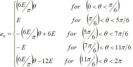
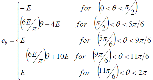
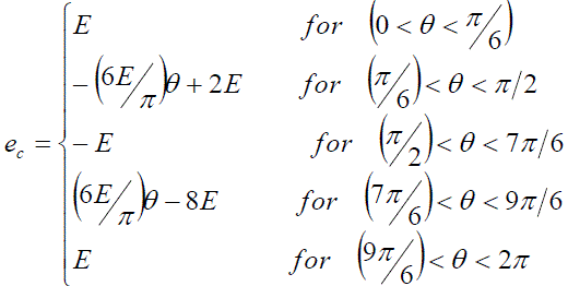
| The back EMF is a function of rotor position (θ) as, |
 |
| Where x can be phase a, b, or c and fx(θ) represents a function of rotor position with a maximum value ±1, identical to trapezoidal induced EMF, given as, |
 |
 |
 |
| The mechanical torque equation of motion is given by, |
 |
| where ωr is the derivative of rotor position θ, P is the number of poles, Tl is the load torque in Newton meters, J is the moment of inertia in kilogram square meters, and B is the friction coefficient in Newton meter seconds per radian. The derivative of rotor position is given as, |
 |
| These equations represent the dynamic model of the PMBLDC motor. |
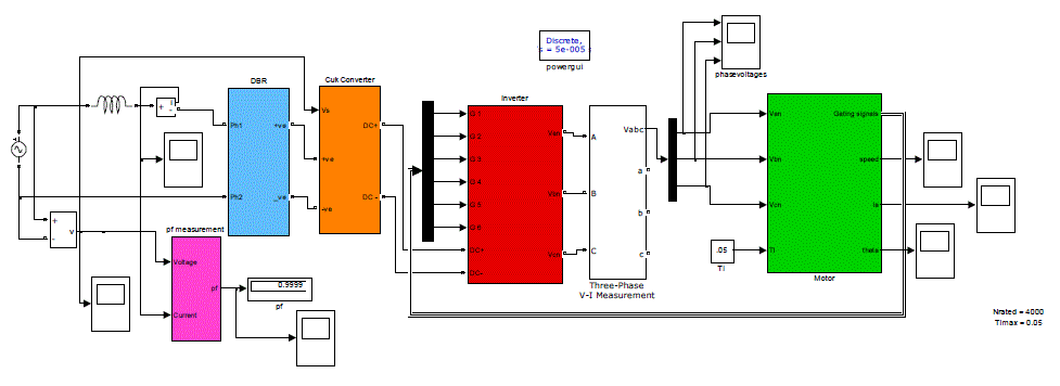
| Fig.5 shows the Matlab model of Permanent Magnet Brushless DC Motor Drive. |
SIMULATION RESULTS
|
| The simulations are done in Matlab simulink. The supply voltage is set to 12V. The Cuk converter step up this voltage to 24V and is fed to the motor. The motor parameters are given in table 1. The simulation wave forms are given below. |
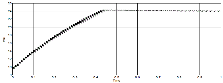
| Following fig.6 to fig.9 shows the variation of single-phase ac supply voltage (Vs), source current (Is), dc link voltage (Vdc), motor speed with time. It can be seen from fig.6 that the input current remains sinusoidal and is found to be in time phase with the input voltage (fig.7). The supply current during starting is distortion free and therefore the operating power factor is close to unity. It can be seen from fig.8 & fig. 9 that as the dc link voltage increases, the motor picks up speed and reaches the final steady value at 0.42 seconds. Once the motor attains the steady speed, the supply current also decreases due to absence of accelerating torque. During starting of the motor the supply current is found to increase with the speed because the power demand of the system is proportional to the speed (the load torque being constant). |
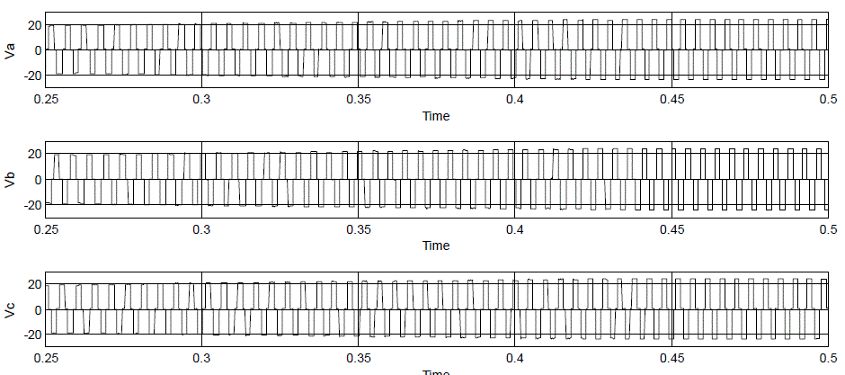
| Fig. 10 & fig.11 shows the rotor position and motor phase voltage. |
CONCLUSION
|
| In this paper, the design of a Cuk converter fed BLDC motor drive is performed and is modeled in Matlab environment. The speed of the motor drive can be varied by changing the dc link voltage of Cuk Converter. It is found that the speed of PMBLDCM has been proportional to the dc link voltage; thereby, a smooth speed control is observed while controlling the dc link voltage. The PFC Cuk converter has ensured near unity power factor in a wide range of the speed and the input ac voltage. |
Tables at a glance
|
 |
| Table 1 |
|
Figures at a glance
|
 |
 |
 |
 |
| Figure 1 |
Figure 2 |
Figure 3 |
Figure 4 |
 |
 |
 |
 |
| Figure 5 |
Figure 6 |
Figure 7 |
Figure 8 |
 |
 |
 |
| Figure 9 |
Figure 10 |
Figure 11 |
|
References
|
- T. Kenjo and S. Nagamori, Permanent Magnet Brushless DC Motors. Oxford, U.K.: Clarendon, 1985.
- Tze-Yee Ho, Mu-Song Chen, Lung-Hsian Yang, Wei-Lun, Lin, “The Design of a High Power Factor Brushless DC Motor Drive”, InternationalSymposium on Computer, Consumer and Control,2012
- Sanjeev Singh, Member, IEEE, and Bhim Singh, “A Voltage- Controlled PFC Cuk Converter-Based PMBLDCM Drive for Air-Conditioners”, IEEETrans.on Ind. Appl., vol. 48, no. 2, March/April 2012
- B. Singh, B. N. Singh, A. Chandra, K. Al-Haddad, A. Pandey, and D. P. Kothari, “A review of single-phase improved power quality ac–dc converters,”IEEE Trans. Ind. Electron., vol. 50, no. 5, pp. 962–981, Oct. 2003.
- N. Mohan, M. Undeland, and W. P. Robbins, Power Electronics: Converters, Applications and Design. Hoboken, NJ: Wiley, 1995.
- Daniel W Hart, Power Electronics
|