Keywords
|
| Maximum power point (MPP); Maximum power point tracking (MPPT); photovoltaic (PV); comparative study; PV Converter. |
INTRODUCTION
|
| Renewable energy is the energy which comes from natural resources such as sunlight, wind, rain, tides and geothermal heat. These sources are renewable and can be natural. Therefore, for all practical purposes, these resources can be considered to be inexhaustible, unlike conventional fossil fuels. The global energy crunch has provided a renewed impact to the growth and development of Clean and Renewable Energy sources. Apart from the rapidly decreasing reserves of fossil fuels in the world, another major factor working against fossil fuels is the pollution unlike their conventional counterparts. Solar energy is one of the most important renewable energy sources. As opposed to conventional unrenewable resources such as gasoline, coal, etc…., solar energy is clean, inexhaustible and free. The main applications of PV systems are in either stand-alone (water pumping, domestic and street lighting, electric vehicles, military and space applications) or grid-connected configurations (hybrid systems, power plants). Unfortunately, PV generation systems have two major problems: the conversion efficiency of electric power generation is very low especially under low irradiation conditions, and the amount of electric power generated by solar arrays changes continuously with weather conditions. Moreover, the solar cell V-I characteristic is nonlinear and varies with irradiation and temperature. In general, there is a unique point on the V-I or V-P curve, called the Maximum Power Point (MPP),at which the entire PV system (array, converter, etc….) operates with maximum efficiency and produces its maximum output power. The location of the MPP is not known, but can be located, either through calculation models or by search algorithms. Therefore Maximum Power Point Tracking (MPPT) techniques are needed to maintain the PV array’s operating point at its MPP. |
MPPT
|
| The photovoltaic module operates at on the I-V characteristic that is determined by the load. Since the power harvested from the photovoltaic module is at different operating points it is important that the load is matched in such a way that maximum power is obtained from the module. |
| Maximum Power Point Tracking, frequently referred to as MPPT, is an electronic system that operates the Photovoltaic (PV) modules in a manner that allows the modules to produce all the power they are capable of. MPPT is not a mechanical tracking system that “physically moves” the modules to make them point more directly at the sun. Maximum power point tracking system is a fully electronics system that varies the electrical operating point of the modules so that the modules are able to deliver maximum available power. Additional power harvested from the modules is then made available as increased battery charge current. MPPT can be used in conjunction with a mechanical tracking system, but the two systems are completely different. |
A. Temperature and irradiation Effects
|
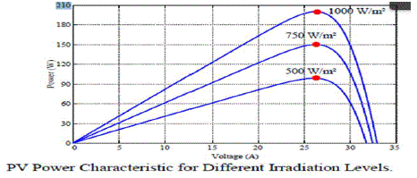
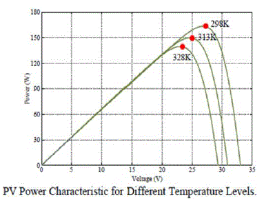
| Two important factors that have to be taken into account are the irradiation and the temperature. They strongly affect the characteristics of solar modules. The maximum available power supplied by a solar array depends on solar irradiation level and ambient temperature. As a result, the MPP varies during the day and that is the main reason why the MPP must constantly be tracked and ensure that the maximum available power is obtained from the panel. |
| The photo-generated current is directly proportional to the irradiance level, so an increment in the irradiation leads to a higher photo-generated current; therefore it is directly proportional to the irradiance. When the operating point is not the short circuit, in which no power is generated, the photo generated current is also the main factor in the PV current. For this reason the voltage –current characteristic varieswith the irradiation. |
| There are many MPPT techniques available here we use the P&Q method and Fuzzy logic. |
MPPT METHODS
|
Perturb-and-observe (P&Q) Method.
|
| The perturb-and-observe method, also known as perturbation method, is the most commonly used MPPT algorithm in commercial PV products. This is essentially a “trial and error” method. The PV controller increases the reference for the inverter output power is indeed increased, it will increase again until the output power starts to decrease, at which the controller decreases the reference to avoid collapse of the PV output due to the highly non-linear PV characteristic. Although the P&Q algorithm is easy to implement, it has a number of problems, including 1) the PV system cannot always operate at the maximum power point due to the slow trial and error process, and thus the solar energy from the PV arrays are not fully utilized; 2) the PV system may always operate in an oscillating mode even with a steady-state sunshine condition, leading to fluctuating inverter output: and 3) the operation of the PV system may fail to track the maximum power point due to the sudden changes in sunshine. Although the P&Q algorithm is easy to implement, it has a number of problems, including 1) the PV system cannot always operate at the maximum power point due to the slow trial and error process, and thus the solar energy from the PV arrays are not fully utilized; 2)the PV system may always operate in an oscillating mode even with a steady-state sunshine condition, leading to fluctuating inverter output; and 3) the operation of the PV system may fail to track the maximum power point due to the sudden changes in sunshine. Perturb-and-observe (P&Q) method is dominantly used in practical PV systems for the MPPT control due to its simple implementation, high reliability, and tracking efficient power. |
Fuzzy logic
|
| Since the PV array exhibits a non-linear current voltage or power voltage characteristic, its maximum power point varies with the insulation and temperature. Some algorithms such as fuzzy logic or artificial neural network control with non-linear and adaptive in nature fit the PV control. By knowledge based fuzzy rules, fuzzy control can track maximum power point. A neural network control operates like a black box model, requiring no detailed information about the PV system. After learning relation between maximum power point voltage and open circuit voltage or insulation and temperature, the neural network control can track the maximum power point online. The disadvantage of these controls is the high cost of implementation owing to complex algorithms that usually need a DSP as their computing platform. |
Working
|
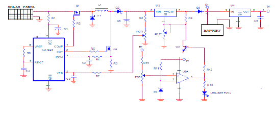
| In our adopted MPPT circuit, the maximum power point is tracked using an IC UC3843. It uses perturb and observe (P&Q) algorithm and Fuzzy logic.UC3843 is an 8pin dip package. It has eight pin and working voltage is 8-20 V. The main advantage of this IC UC3843 is that there is no need ofmuch outside components. In this IC there are two PWM (Pulse Width Modulation) generating pins, OUT and COMP. And there is a feedback pin too. The feedback topology is made used here. The feedback voltage of IC UC3843 is 2.5 V. Using a potentional divider arrangement R8 and POT 1 are designed in such a way that 2.5 V should get at the feedback pin of the IC UC3843 when panel voltage is 15 V. At that time the duty cycle of two PWM is remains same. Out of two PWM, one is connected to a MOSFET Q1, which act as a buck converter and PWM 2 is connected to a MOSFET Q2, which act as a boost converter. |
CIRCUIT DIAGRAM OF MPPT
|
| Depending on the voltage to the feedback pin, the IC select which PWM should operate. Boost converter is used to set up the input voltage and buck converter is used to step down the voltage. Hence a buck-boost converter is used here. MOSFET Q1 & Q2, inductor L1, diode D2 & D1 etc comprises of buck-boost converter. If the panel voltage is 15 V then feedback pin voltage falls below 15 V then the voltage across feedback pin also get lowered. Then duty cycle of out pin of IC UC3843 will increased, the increase is made until when voltage across feedback pin is 2.5 V. During this time COMP of IC 3843 is made 0 % and only PWM OUT is changes its duty cycle accordingly with the feedback pin voltage. When the panel voltage is increased beyond 15 V then voltage across feedback pin increased then initially the duty cycle of OUT PWM is reduced from its present value. The duty cycle of OUT PWM can be reduced to about 10%. Below this we cannot reduce the duty ratio. Even then the voltage in the feedback pin is greater than 2.5 V, then buck PWM starts its operation. (All the other time the buck PWM is made 0 %). The duty cycle COMP PWM for IC 3843 the third pin ISEN is called as current sensing. The voltage across ISEN pin is designed in such a way that one volt should come across it. It is used to protect the MOSFET Q1 & Q2 and the inductor L1. The protection is made by limiting the flow of current. The resistor R3 is designed in such a way that maximum of 2 A is allowed to flow. |
| Resistor R6 and capacitor C4 in IC 3843 is selected as 10 K & 0.1 microfarad respectively. It is so selected that a 40 KHz is the operating frequency. These values are selected from the data sheet of IC 3843. |
| The supply to the IC3843 is get from the solar panel directly via a resistor R1, thus the resistor act as a fuse, if a short circuit occurs at IC then solar panel get protected. Another function of R1 &C1 is that it acts as a high frequency filter and avoid oscillation problem.The resistor R2 & R5 is used to reduce the gate current of the two MOSFET Q1 & Q2 respectively. Resistor R4 and capacitor C2, and resistor R7 and capacitor C3 are use as high frequency filter to avoid frequency switching. The inductor L1 is selected as 100 micro hertz, it is so selected that for an operating frequency of 40 KHz, 100 micro hertz is necessary. Capacitor C5 is used to filter the pulsating dc to pure dc. |
Battery
|
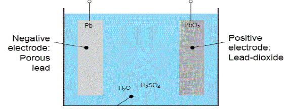
| The main factor affecting the battery life of a lead acid battery is overcharging. Overcharging of a lead acid battery leads to electrolysis of water and generation of hydrogen gas, electrolysis of other components in electrodes and electrolyte which can generate poisonous gases, bulging and deformation of cases of sealed batteries. Hence overcharge protection circuit is essential along with all batter, in order to increase the life cycle. |
Overcharge protection Circuit
|
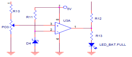
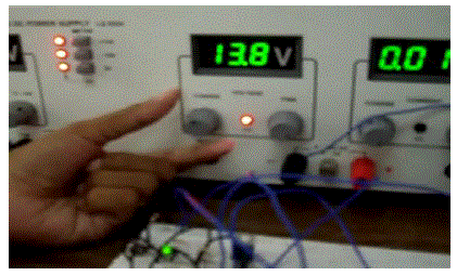
| In our adopted overcharge protection circuit,the main electronic component is an operational amplifier or Op-amp which act as a cmparator. It compare whether the battery voltage reaches 13.8 V. If not it continous thecharging process,and if yes,the supply is disconnected from the voltage. |
| Here, we use LM358 Op-amp, which is a 8 pin dual in package and there is two op-amp in this name IC. |
| The comparator compare whether the inverting or non-inverting terminal voltage is greater. If the inverting terminal voltage is greater, the output of Op-amp is an active low and if non-inverting terminal voltage is greater than inverting terminal voltage,the output is the an active high state. If the battery voltage is lesser than the upper threshold value,the voltage across the non-inverting terminal is less than 3V, and thus inverting termial having 3V is greater, hence the output is in active low state. The output of comparator is connected to an LED and to a NPN transistor Q3. The LED is used to indicate whether the battery is fully charged or not. If it lights up shows that the battery is fully charged. The collector terminal of the NPN transistor Q3 is connected to the adjust pin of voltage regulator LM 317. If the adjust pin is zero the IC LM 317 will shut down its operation and thus cut the supply to battery. |
| If the battery voltage is less than 13.8 V, then voltage across pin 3 of IC LM 358 is lesser than 3V and the voltage across pin 2 is 3V. Then an output of an Op-amp IC LM358 is zero. Hence the NPN transistor Q3 in OFF state. And hence voltage regulators IC LM 317 provide supply to charge the battery and LED is not charging. When the battery voltage is greater than 13.8 V, then voltage across non-inverting terminal is greater than 3 V and the voltage across the inverting terminal is 3 V itself. Hence the output of an Op-amp is high. Thus the NPN transistor will made ON. Since the output of the comparator is given to the base of the transistor and the voltage is grounded. Hence the voltage across adjust pin of voltage regulator IC LM 317 is zero, so the IC LM 317 will stop operation and prevent providing supply from solar panel to battery until the battery voltage fails behind 1.8 V. The LED will start glow, indicate that the battery is in its full charge condition. The NPN transistor is used to cut off the supply to battery, when output of op-amp is one, hence we can protect battery from overcharging. |
| The resistor R 11, R22, R33 is used to limit the current flow through Zener diode, D4,,NPN transistor Q3 and LD respectively. Port 3 and R10 is designed in such a way that 3V will appear across when the battery voltage is 13.8 V. The design is based on voltage division rule. |
| The shutdown pin of inverter IC is used as to cut off the supply from battery when the output of the op-amp is one, hence we can protect battery from over discharging. |
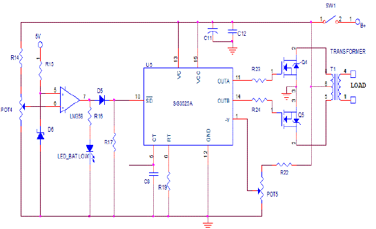
| When the shut down pin of inverter is one, the two PWM pin 11 and 14 work with complementary output. When the shut down pin becomes zero, the IC will not work and provide no PWM. Diode D5 is used to prevent the flow of current from inverter to LM 358. Since output voltage is 12 V and LM 358 IC have only 5 V. |
Over discharging protection
|
| The main factor affecting the Lead-acid battery is over discharge. Over discharge of lead acid battery leads to sulfation and the battery ruined. The reaction becomes irreversible when the size of the lead-sulphate formation becomes too large. Hence over discharge protection circuit is essential along with the battery,inorder to increase the life cycle. In a 12 V lead-acid battery the lower threshold voltage range is limited to 10-8 V. In our case we use lower threshold voltage of lead acid battery is 10 V. It is selected so as to increase life of battery. |
| In over discharge protection circuit, when the battery voltage reaches lower threshold voltage when the battery voltage reaches lower threshold voltage then the inverter operation get stopped.(Monitoring the battery voltage every time manually is not an easy process, and connecting and disconnecting supply every time sometimes lead to sparking. Hence there is need arise for the automatic disconnection of supply from battery when charge to reach lower threshold voltage. |
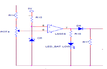
| In our adopted over discharge protection circuit the main electronic component is an operational amplifier or op-amp which act as a comparator. It compare whether the battery voltage reaches lower threshold voltage. |
| The battery voltage is given to the inverting terminal of the comparator. And a 3V is given to the non-inverting terminal through a zener diode. Zener diode clip the input 5V to 3V. The input 5V is obtained using a fixed voltage regulator LM 7805. It is a three terminal IC have three pins as IN,OUT and GND. It is used to get 5V at OUT pin,if the input is greater than 6V. If the input is less than5V output is zero. Therefore minimum 6V is required to turn on IC LM 7805. |
| The comparator compare whether the inverting terminal voltage is greater. If the inverting terminal voltage is greater,the output of op-amp is an active low and if non-inverting terminal voltage is greaterthan inverting terminal voltage, the output is an active high state. If the battery voltage is lesser than lower threshold value, the voltage across the inverting terminal is less than 3V, and thus non-inverting terminal having 3V is greater,hence the output is an active low state. The output of comparator is connected to an LED. The LED is used to indicate whether the battery reaches its lower threshold value. If it lights up shows that the battery reaches its lower threshold value. |
| The output of LM 358 is connected to the shutdown pin of inverter IC SG3525. When voltage of battery gets below threshold voltage the IC SG3525 is shut down and thus protect the battery from over discharging. |
Inverters
|
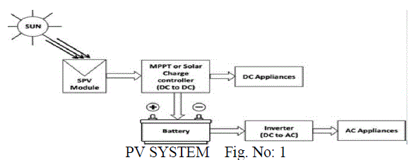
| The PV arrays produce DC power and therefore when the stand-alone pv system contains an AC load then a DC/AC conversion is required. This is thus the reason why this section briefly presents the inverter. An inverter is a converter where the power flow is from the DC to AC side,namely DC voltage. |
Working
|
| Invertor converts the stored dc energy into ac. For inductive load such as a fan,we prefer sine wave inverter. In our case the load is a CFL lamp,hence square wave inverter is sufficient. |
| Consider a transformer a switch is connected to primary winding and load is connected to other winding. When dc voltage is given to primary of the transformer & switch is open, then no current will flows. When switch is closed then due to flux an emf will induce in secondary. Hence by controlling the turn on and off the switch,we can say vary the secondary voltage of the transformer the waveform will be square shaped one. |
| In the above circuit for the generation of PWM, two MOSFETS Q5 & Q4 used, for the working of these MOSFETS, we use an IC SG3525. SG3525 is a 16 pin dip. The working voltage of this IC is 8V to 15V & operating frequency of SG3525 is 50 Hz to 200KHz. It provide two PWM with complimentary output.If the shut down pin is zero then IC will get shut down that its stop working. The load is a CFL lamp which operates in 50 Hz ac. The value of resistor and capacitor in RT &CT pins of SG 3525 determines the frequency of operation,hence R19 &C8 is designed in such a way that the operating frequency is 50 Hz .The working voltage to the IC is given through battery. The transformer used here is center tapped transformer. Battery voltage is given to the center tapped winding of the transformer and two switches are provided at two ends of the primary of the transformer. The switches used here is an electric switch like MOSFET. The PWM for this MOSFET is get from the IC SG3525. The OUT A & OUT B terminal i:e, pin 11 & 14 of SG3525 provide PWM with complimentary output. |
| When OUTA terminal of IC SG3525 is provide PWM then MOSFET Q4 is turned ON, and current flow is from pin 6 to pin 8 of transformer. At these times Q5 is turned OFF, asthe PWM from OUTB is absent. When OUT B terminal if IC SG3525 is provide the PWM, then the MOSFET Q5 is turned ON and now current flow is from point 6 to point 5 of transformer. That is the current flow is reversed from the previous case, hence we get a square wave of positive and negative half cycle. So by adjusting the switching & duty cycle we can provide an alternating waveform. |
| The transformer used here is a 12/230V transformer. Hence thevoltage of the secondary of the transformer is 230 V; hence we can connect a CFL lamp as load. In order to adjust the voltage across the load port 5 is varied. If the voltage to the pin 1 of IC SG3525 is 2.5V, then the duty cycle of the IC will work in same dc. The voltage 2.5V is adjusted using port5. A switch sw1 is provided in order to control the operation of the inverter. If SW1 is closed, then only the inverter starts operation. This switch is a mechanical switch and is manually operated. The inverter operation gets interrupted when an active low signal is given across the shut down pin of IC 3525. Resistor R23 and R34 is usedto limit the gate current of the MOSFET Q4 &Q5 respectively. |
CONCLUSION
|
| Currently the usage of energy from photovoltaic panel is a reality, and its intensive use will become extremely important in finding solutions to energyrelated problems and environmental problems very soon. Photovoltaic panel is used to derive energy from sun. The solar cell V-I characteristic is nonlinear and varies with irradiation and temperature. In general, there is a unique point on the V-I or V-P curve, called the Maximum Power Point (MPP), at which the entire PV system (array, converter, etc….) operates with maximum efficiency and produces its maximum output power. The location of the MPP is not known, but can be located, either through calculation modelsor by such an algorithms. Therefore Maximum PowerPointTracking (MPPT) techniques are needed to maintain the PV array’s operating point at its MPP. |
Figures at a glance
|
 |
 |
 |
 |
 |
| Figure 1 |
Figure 2 |
Figure 3 |
Figure 4 |
Figure 5 |
 |
 |
 |
 |
 |
| Figure 6 |
Figure 7 |
Figure 8 |
Figure 9 |
Figure 10 |
|
References
|
- G.W.Rong-Jong and W.Wen-hung, “Grid-connected photovoltaic generation system,” IEEE Trans. Circuit Syst. I, Reg& Papers,vol.55,pp.953-964,2008.Z . Liang, R. Guo, and A.Huang, “ A new cost-effective analog maximum power point tracker for PV systems,” Proc. IEEE Energy
- Convers. Congr.Expo.(ECCE), pp, 624-631,2010.
- D.Sera, T.Kerekes, R. Teodorescu, and F.Blaabjerg, “Improved MPPT algorithms for rapidly changing environmental conditions,”inProc,Power Electron. Motion Control. Conf,(EPE-PEMC),2006,pp. 1614-1619.
- C.Drofte, U. Borup, and F.Blaabjerg,”A combined two-method MPPT control scheme for grid-connected photovoltaic system,”inProc. Ear.Conf. Power Electron. Appl.,2005,p. 10.
- Walker,Geoff,Evaluating MPPT converter topologies using a matlab PV model, journal of electrical and electronics engineering, Australia,Vol21,2001,pp 49-55.
- HSIEH, G.C;.at all Variable Frequency Controlled Incremental Conductance Derived MPPT Photovoltaic stand-along DC bus system.inc.APEC ,23,2008,p, 1849-1854.
- KWON,J.;etal.photovoltaic Power Conditioning System with line connection IEEE Transactions on Industrial Electronics, New York,v.53,n.5;p. 1048-1054 ,2006.
- YU, W.L.; et al. A DSP- Based Single–Stage Maximum Power Point Tracking PV inverter. IN : APEC ,25, 200, P. 948-952.
- HO,B.M.T.;et al. Use of system Oscilliation to locate the MPP of PV Panels. IEEE Power Electronics Letters, V.2,n1p..5,2004.
- HASAN,K.N.:et al. An improved maximum power point tracking technique for the photovoltaic module with current mode control. In:AUPEC, 9,2009,p.1-6.
- CHUNG,H.S;ET AL. A maximum power point tracking technique for solar panels using a SEPIC or Cuk Converter. IEEE Transactions onPower Electronics,v.8,n3,p.77-724,2003
|