Keywords
|
| MLA, LTE, WLAN, RFID, FR4, CPW |
INTRODUCTION
|
| The development of small integrated printed antennas plays a significant role in the progress of rapidly expanding wireless communication applications. They are increasingly used in wireless communication systems due to advantages of being lightweight, compact, conformal, good efficiency and bandwidth. In mobile communications, meander line antennas are recently favoured over other printed antennas due to its simplicity and ease in integration. A more compact design of a meander line antenna was designed to operate at 2.4-GHz for WLAN application [7]. The designed antennas were fabricated on a double-sided FR-4 printed circuit board using standard PCB technique and tested with a Network Analyzer. The effect on the antenna radiation and reflection properties with varying the MLA length, Width, number of turns and conductor dimensions are also discussed in this paper. Meander Line Antenna is a type of printed antenna that achieves miniaturization in size by embedding the wire structure on a dielectric substrate. MLA technology was originally developed by BAE SYSTEMS (a former Lockheed Martin Company) , for the Information and Electronic Warfare Systems (IEWS), which require high performance antennas for both satellite and terrestrial communications. Recently, this class of antennas are found to be suitable for application mobile handsets; wireless data networking for laptops,[3] PC cards and access points. In basic form meander line antenna is a combination of conventional wire and planer strip line. Artificial Magnetic Conductors are used to improve efficiency and bandwidth of MLA. Benefits include configuration simplicity, easy integration to a wireless device, inexpensive and potential for low Specific Absorption Rate (SAR) features. SAR is a measure of the rate at which energy is absorbed by the body when exposed to a radio frequency (RF) electromagnetic field. It is defined as the power absorbed per mass of tissue and has units of watts per kilogram. |
LITERATURE SURVEY
|
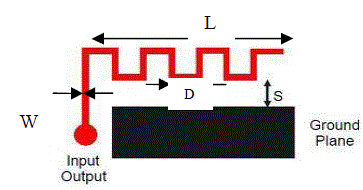
| In a meander line antenna (also called rampart line antenna), the radiating element consists of a meandering micro strip line formed by a series of sets of right angled compensated bends, as shown in Figure 2.1 The fundamental element in this case is formed by four right angled bends and the radiation mainly occurs from the discontinuities (bend) of the structure.[1] The right angle bends are chamfered or compensated to reduce the right angled discontinuity susceptance for impedance matching. The current directions are changing in every half wavelength and there are more than four half wavelength changes in this design. The radiations from the bend add up to produce the desired polarization depending on the dimensions of the meander line antenna. The electrical small antenna defines as the largest dimension of the antenna is no more than one-tenth of a wavelength [10]. Meander antenna is electrically small antenna .The design of meander line antenna is a set of horizontal and vertical lines. Combination of horizontal and vertical lines forms turns. Number of turns increases efficiency increases. In case of meander line if meander spacing is increase resonant frequency decreases. At the same meander separation increase resonant frequency decreases [11]. A meander antenna is an extension of the basic folded antenna and frequencies much lower than resonances of a single element antenna of equal length. |
| Three types of feed structure can be implemented in proposed antenna: |
| 1. CPW feed (Coplanar Waveguide) |
| 2. Inset Feed |
| 3. Microstrip Feed |
| Coplanar waveguide is a type of electrical transmission line which can be fabricated using printed circuit board technology, and is used to convey microwave-frequency signals. On a smaller scale, coplanar waveguide transmission lines are also built into monolithic microwave integrated circuits. [2] |
| Microstrip line feed is one of the easier methods to fabricate as it is a just conducting strip connecting to the patch and therefore can be consider as extension of patch. It is simple to model and easy to match by controlling the inset position. However the disadvantage of this method is that as substrate thickness increases, surface wave and spurious feed radiation increases which limit the bandwidth. |
| Advantages of CPW over Microstrip Feed: |
| a. Low Dispersion |
| b. Low Radiation Leakage |
| c. Ground plane not interdependent |
| d. Radiation from feed structure is negligible because of coplanar waveguide is excited in odd mode of coupled slot. This feature is useful in design of antenna arrays since mutual coupling between adjacent lines is minimized. |
| Inset fed is technique where the path of feed is pushed at a particular distance to match impedance This typically yields high input impedance. Since the current is low at the ends of a half wave patch and increases in magnitude toward the centre, the input impedance could be reduced if the patch was fed closer to the centre. |
PRINCIPLE
|
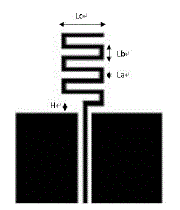
| The meander-line antenna can be in a dipole or ground plane format. The idea is to fold the conductors back and forth to make the overall antenna shorter, which is shown in Figure 3.1. It is a smaller area, but the radiation resistance, efficiency and bandwidth decrease [9]. The parameters of meander shape, for example H, La, Lb and Lc shown as in the figure will affect the antenna performance parameter [8]. In order to find the best antenna solution, different values of meander width are simulated and studied. (actual report MLA). |
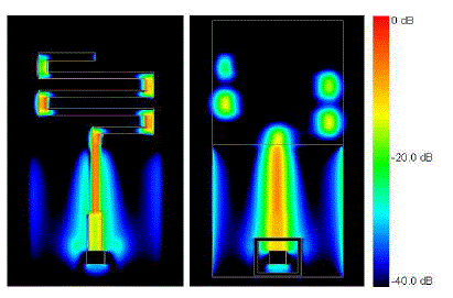
| A meander-line antenna can be realized by bending the conventional linear monopole antenna to decrease the size of antenna [5]. The influence of the meander part of the antenna is similar to a load and the meander line sections are considered as shorted-terminated transmission lines as shown in Figure 3.2. The meander line section can be modeled as an equivalent inductor. In the far-field pattern, in the result of the cancellation of magnetical fields, the transmission lines of a meander line antenna do not radiate fields. The radiation fields will be radiated from the vertical pars of MLA. The currents intension of vertical parts can be clearly seen in Figure 3.3. |
MLA CONFIGURATIONS
|
MLA with Different Thickness of Vertical Segment
|
| An important application of meander line antenna is in wireless Communication systems such as WLAN. In these applications, bandwidth is an important factor. As it mentioned before meander line antenna has low efficiency [5]. So if this kind of antenna wants to use in WLAN systems, it must to improve it bandwidth. |
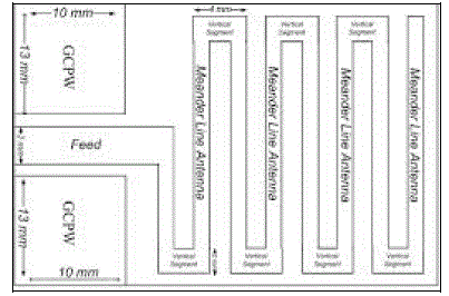
| If we analysis current distribution of classic meander line antennas it could be observed that vertical segment of meander line antenna has more role in constructing electrical field of this antenna. Therefore, with applying some changes in this segment, such as different thickness, it might get better results. Figure.4.1 shows MLA with different thickness of vertical segment. In this structure, thickness of vertical segment and feed line are 2mm and thickness of horizontal segment is 1 mm. |
Log Periodic Meander Line Antenna
|
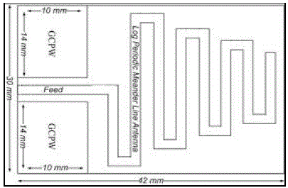
| The increasing use of wireless communication systems, demands the antennas for different systems and standards with properties like compact, broadband and multiple resonant frequencies. Classic meander line antenna is able to perform in single band. Log periodic antenna is a kind of frequency independent antenna and is able to achieve multi-band performance [6]. Therefore, log periodic technique has been combined with classic meander line antenna to get dual band antenna. Figure.4.2 shows illustration of this antenna. |
Symmetrical Meander Line Antenna
|
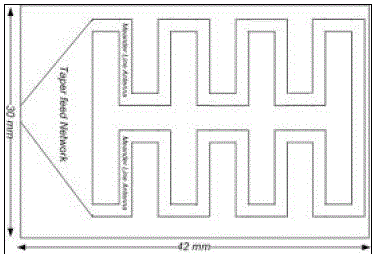
| Nowadays, communication devices which have more properties are more usable than other devices. One of its properties is devices that able to operate in dual band frequencies [6]. As it mentioned before, log periodic MLA approach is one of them. Another technique to get dual-band resonance is two segment MLA. In this mode main antenna, composes in two sub MLA. Each one can be designed to operate in one resonance frequency. |
| These segments can be symmetrical or asymmetrical [6]. Figure 4.3 shows the illustration of this antenna. In this structure taper plane has been designed to get better matching network. |
SIMULATION & RESULTS WITHOUT AMC
|
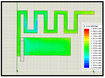
| The final design in HFSS is as shown in figure 5.1 above. It shows the electric field distribution throughout the antenna. Design is without Artificial Magnetic Conductor. Design is completed in HFSS version 11 and simulated in the same. |
| 1. By changing Width (gap) of MLA |
| As given in table 5.1 we can see that how the bandwidth is changes as the gap of Meanders changes which can be used as to improve the bandwidth and efficiency of MLA. |
| 2. By changing Height of MLA |
| As shown in table 5.2 come also we can see that bandwidth can be improved with the help of gap changes .Finally it can be concluded that many ways of improvement of bandwidth are there as slotting of antenna, artificial magnetic conductor and so on. |
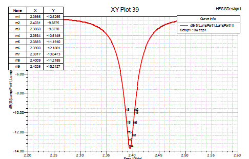
| As shown in figure 5.2 return loss of 2.4 GHz MLA shows -11 Db at 2.4009 frequencies. This can be further reduced and improved by artificial magnetic conductor. Also many other features such as bandwidth, efficiency can be improved using AMC. |
DESIGN, SIMULATION AND RESULTS OF MLA WITH AMC
|
| AMC is an artificial, metallic, electromagnetic structure. The structure is designed to be selective in supporting surface wave currents, different from conventional metallic conductors. It has applications for microwave circuits and antennas. As an antenna ground plane it suppresses the propagation of surface waves, and deployed as an improvement over the flat metal sheet as a ground plane, or reflector. Hence, this strategy tends to upgrade the performance of the selected antenna. Strong surface waves of sufficient strength, which propagate on the metal ground plane will reach the edge and propagate into free space. This creates a multi-path interference. In contrast the AMC surface suppresses the propagation of surface waves. Furthermore, control of the radio frequency or microwave radiation pattern is efficiently increased, and mutual between antennas is also reduced First, AMC surfaces are designed to have an allotted set of frequencies over which electromagnetic surface waves and currents will not be allowed to propagate. These materials are then both beneficial and practical as antenna ground planes, small flat signal processing filters, or filters as part of waveguide structures. For example, AMC surfaces as antenna ground planes are able to effectively attenuate undesirable wave fluctuations, or undulations, while producing good radiation patterns. This is because the material can suppress surface wave propagation within the prescribed range of forbidden frequencies. Second, AMC surfaces have very high surface impedance within a specific frequency range, where the tangential magnetic field is small, even with a large electric field along the surface. Therefore, an AMC surface can have a reflection coefficient of +1. |
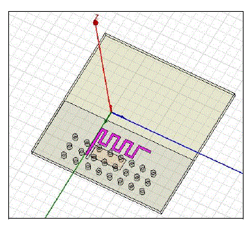
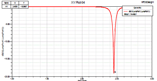
| Figure 6.1 shows HFSS design of MLA with artificial magnetic conductor which is designed at lower part of MLA from the feed line. The next figure 6.2 shows the simulation results of MLA with AMC, the return loss which is -18db at 2.40 GHz which shows that return loss is improved and hence other parameters. |
| As per shown in the return loss above figure 6.2 we can see that the return loss is improved as per existing system shown before in figure 5.2 with which other parameters also get improved . |
CONCLUSION
|
| Meander line antenna has good properties such as, small, low profile, simple and cheap. These nice features make meander line antenna very popular and usable in many aspect of communication systems such as RFID and WLAN. In this project, planar MLA with inset feed has been designed. A Meander Line Antenna (MLA) with artificial magnetic conductor for 2.4 GHz is proposed and implemented. This research focuses on the optimum value of gain and reflection coefficient. Therefore, the MLA's parametric studies are discussed which involved the Height of substrate and Gap between turns and number of turns. Hence the return loss and other parameters are been improved with the help of artificial magnetic conductor. The MLA also resembles the monopole antenna behavior of Omni-directional radiation pattern. Measured and simulated results are presented. The proposed antenna has big potential to be implemented for Wireless devices such as mobile phones, tabs etc. |
Tables at a glance
|
 |
 |
| Table 1 |
Table 2 |
|
Figures at a glance
|
 |
 |
 |
 |
| Figure 1 |
Figure 2 |
Figure 3 |
Figure 4 |
 |
 |
 |
 |
| Figure 5 |
Figure 6 |
Figure 7 |
Figure 8 |
 |
 |
 |
| Figure 9 |
Figure 10 |
Figure 11 |
|
References
|
- Shao-Li Zuo, Zhi-Ya Zhang, and Jia-Wei Yang ,”Planar Meander Monopole Antenna With Parasitic Strips and Sleeve Feed for DVBH/LTE/GSM850/900 Operation in the Mobile Phone” , IEEE ANTENNAS AND WIRELESS PROPAGATION LETTERS, VOL. 12, 2013
- Nassrin Ibrahim Mohamed Elamin, TharekAbdRahman, and Amuda Yusuf Abdulrahman, “New Adjustable Slot Meander Patch Antenna for 4GHandheld Devices”, IEEE ANTENNAS AND WIRELESS PROPAGATION LETTERS, VOL. 12, 2013.
- Frank M Caimi.(2002) SkyCross.Inc.
- D. Misman1, I. A. Salamat1, M. F. Abdul Kadir1, M. R. Che Rose1, M. S. R. Mohd Shah1, M. Z.A. Abd. Aziz1, M. N. Husain1, P.J Soh2,” TheStudy of Different Impedance Meander Line for Planar Antenna Design “.
- Balanis, C. A.,” Antenna Theory Analysis and Design”, 3rd edition, Copyright 2005 by John Wiley & Sons, Inc., 2005.
- A.Jahanbakhshi1, Gh.Moradi2, and R. Sarraf Shirazi2,”Design and Simulation of Different Types of Meander Line Antennas with ImprovedEfficiency”, 1Amirkabir University of Technology, Iran Electrical Department, Amirkabir University of Technology, Iran.
- C.-C. Lin , S.-W. Kuo and H.-R. Chuang, “2.4-GHz Printed Meander-Line Antenna for USBWLAN with Notebook-PC Housing.” StudentMember, IEEE
- I-Fong Chen and Chia-Mei Peng, “Compact Modified Pentaband Meander-Line Antenna for Mobile Handsets Applications”, IEEE ANTENNASAND WIRELESS PROPAGATION LETTERS, VOL. 10, 2011.
- Louis E. Frenzel, Louis E, “Printed-Circuit-Board Antennas”, Frenzel, pp.1-2, March 31, 2005.
- D. Miron, Small Antenna Design, Newnes 2006.
- S.R Best and J.D Morrow, “Limitations of Inductive Circuit Model Representations of meander line antennas”.,vol. 1,pp 852-855,IEEE Trans.Antennas and Propagation Society International Symposium ,June 2003.
|