ISSN: 2229-371X
ISSN: 2229-371X
Beenish Zia1*, Xiang Guo1, Yong Tong Chua1, Thomas Labno2
1 Intel Corporation, Santa Clara, California, USA
2 Canon Medical Research, Illinois, USA
Received: 06-Sep-2024, Manuscript No. GRCS-24-147592; Editor assigned: 09-Sep-2024, PreQC No. GRCS-24-147592 (PQ); Reviewed: 23-Sep-2024, QC No. GRCS-24-147592; Revised: 30- Sep-2024, Manuscript No. GRCS- 24-147592 (R); Published: 07-Oct- 2024, DOI: 10.4172/2229- 371X.15.3.002
Citation: Zia B, et al. Medical Image Reconstruction Optimizations Using Unified Programming Model. J Glob Res Comput Sci. 2024;15:002.
Copyright: © 2024 Zia B, et al. This is an open-access article distributed under the terms of the Creative Commons Attribution License, which permits unrestricted use, distribution, and reproduction in any medium, provided the original author and source are credited.
Visit for more related articles at Journal of Global Research in Computer Sciences
Image reconstruction is the manipulation of digitized information obtained during body imaging into interpretable pictures that represent anatomical details and diseases. It is a vital step in producing visual results from a Computed Tomography (CT), Magnetic Resonance Image (MRI) etc. scanning devices. In all modalities (CT, MRI etc.) the data is acquired in form of slices or projections. In simple terms, the process of putting the projections together in a two-dimensional (2D) or three dimensional (3D) scans can be called image reconstruction. Back projection and forward projections are two commonly used operations in the image reconstruction pipeline. And since the image reconstruction algorithms can be compute intensive, there is desire to fasten the processing time for it, to get the final scan faster. The scans are what a medical professional such as a radiologist use to provide diagnosis to a patient, hence faster access to scan can result in more timely diagnosis. With the goal to reduce the processing time for image reconstruction pipeline, the authors worked to analyse and optimize representative back projection and forward projection algorithms. This document provides details on the various optimization and code migration work that was done to achieve targeted performance metrics using a hardware vendor neutral programming language.
Back projection; Forward projection; Medical imaging; Image reconstruction; Unified programming
Image reconstruction is the manipulation of digitized information obtained during body imaging into interpretable pictures that represent anatomical details and diseases. It is one the compute intensive application in the image generation process of a medical image pipeline, that heavily uses matrix multiplications. Most modalities including CT, MRI, X-Ray, Ultrasound use image reconstruction algorithm in some form or another, however for this paper the authors focus was on image reconstruction algorithms for CT modality.
Images are reconstructed from approximately 1000 such projections acquired as the X-ray tube rotates through 360 degrees around the patient [1]. As mentioned in the image reconstruction techniques article, image reconstruction process impacts image quality and subsequently radiation dose [2]. So, it’s critical that efficient and optimized image reconstruction algorithms be used to produce acceptable image quality with reduced radiation dose.
Back Projection (BPJ) and Forward Projection (FPJ)
An algorithm is a step-by-step mathematical procedure implemented on a computer. In most cases one the two types of algorithms are used for reconstructing a medical image. The first type of algorithm used is analytical algorithms. Here filtered back projection is the most common algorithm. The second type of algorithm used is Iterative algorithm. Iterative reconstruction is becoming popular, since it’s easy to model and handle projection noise as well as it’s easy to model the imaging physics [3].
Analytic reconstruction algorithms, for example the filtered back projection algorithm, are efficient and elegant, but they are unable to handle complicated factors such as scatter. Iterative reconstruction algorithms on the other hand are more versatile but less efficient. Efficient (i.e., fast) iterative algorithms are currently under development. With rapid increases being made in computer speed and memory, iterative reconstruction algorithms will be used in more and more applications and will enable more quantitative reconstructions [4].
The FPJ and BPJ are a key pair in above mentioned medical image reconstruction algorithms. The forward projection is a mathematical model of the physical data acquisition process in CT and tom synthesis and the back projection is the corresponding reverse model.
The FPJ algorithm is used in iterative reconstruction and provides insight into how projection is acquired in CT imaging. FPJ process is an additive operation, where values in each pixel along a specified ray direction is added up. In short, forward projection is the process of adding up all of the pixel values along the measured direction [5].
BPJ is an operation that essentially does the opposite of forward projection. Since the forward projection operation maps the image into the detector space the back projection operation maps from detector back to the image. In short, back projection is used to convert the data from the detector (projection space) to the image space. For the code/algorithm optimization work done by the authors, for back projection the work was limited to circular Feld Kamp (FK) method which is a well-established industry standard for conventional CT back projection [6].
Similarly, for forward projection work was limited to ray-drive approach with 3D interpolation. In both cases, a distance-driven method also exists as well as other ray-driven methods for determining the contribution (Siddons, Nearest-neighbor, etc.). However, even though distance-driven methods have many advantages, they are difficult to optimize due to conditionals, branching and indeterminate loop size and hence was not used in this study. The source code/algorithm (compiled in C++) that was optimized by the authors, covered in next section, was provided by Canon Medical Research for forward projection and backward projection separately, with target performance metric for each. Authors didn’t find publicly available source code for other FPJ and BPJ algorithms that they could use for comparative study, hence only no algorithm comparison has been added. In the rest of the sections, authors will cover details on forward projection and backward projection code migration from C/C++ to Data Parallel C++ (DPC++) and optimization (specifically memory optimizations) of the migrated codes on a selected discrete Graphics Processor Unit (GPU).
Image reconstruction code migration and optimizations
As mentioned, the goal for the authors was to optimize the BPJ and FPJ codes to meet performance metrics that would make the overall imaging pipeline efficient and faster. One the primary steps to this optimization was to migrate the original C/C++ and CUDA dependency code to unified cross-architecture programming language (Data Parallel C++ (DPC++/DPCPP)) using the one Application Programming Interface (API) industry specification, that would allow the code to hardware vendor neutral and portable across a CPU and GPU [7].
To better understand how the code migration and optimization work was done, the authors would like to cover following fundamental topics that are critical to acknowledge before diving into optimization details.
• DPC++ software design.
• Running CPU codes on GPU.
• GPU performance tuning.
Data Parallel C++ (DPC++) software design
Data Parallel C++ (DPC++) is a new direct programming language of one API, an industry initiative to simplify and unify programming across different computing architectures, like CPU, GPU, FPGAs etc. DPC++ based on industry standard C++, incorporates SYCL specification 1.2.1 from the Khronos Group, and includes language extensions developed using an open community process. Purposely designed as an open, cross-industry alternative to single-architecture, proprietary languages, DPC++ enables developers to easily port their code across CPUs, GPUs and FPGAs, and also tune performance for a specific accelerator. Figure 1 shows you a simple example of DPC++ code.
Queues connect a host program to a single device [8]. Figure 2 shows the way queues can be submitted for a device in DPC++
Kernel in simplistic terms is a large block of code which keeps the system up and running from boot-up to shut down.
As explained in the DPC++ book, kernels have emerged in recent years as a powerful means to expressing data parallelism. Portability across variety of devices and programmer productivity are the main goals of kernel-based approach. Hence, kernels are not hard coded to work with specific hardware configuration. Instead, kernels are written in terms of abstract concept that an implementation can then map to the hardware parallelism available on a specific target device [8]. Kernels can be invoked as a) single task b) basic parallel kernel c) hierarchical kernel and d) neutral density-range kernel (N dimensional). Figures 3-5 show examples of one-dimension, two-dimension and three-dimension kernels that will help to understand kernel optimization step in the back projection and forward projection case study in the next section.
The last topic to understand in DPC++ software design is memory management. There are three abstractions for memory management in DPC++. a) Unified Shared Memory (USM) b) buffer and c) images. USM is a pointer-based approach and similar to what C/C++ programming uses.
USM provides easy porting from C/C++. Devices that support USM support a unified virtual address space. Having a unified virtual address space means that any pointer value returned by a USM allocation routine on the host will be a valid pointer value on the device. When system contains both host memory and some number of devices attached local memories, USM creates three different types of allocations: Device, host and shared. Table 1 shows the characteristics of each of these three allocation types [9].
| Memory Type | Accessible on host | Accessible on device | Location |
|---|---|---|---|
| Host | Yes | Yes | Host |
| Device | No | Yes | Device |
| Shared | Yes | Yes | Uncertain |
Table 1. Memory accessibility using USM.
With the understanding of USM, next thing to comprehend is how data gets copied between host and device and once that is done how it is synchronized. Figures 6 and 7, respectively provide examples of doing that.
It’s worth mentioning that DPC++ is implemented using System-wide Computer Language (SYCL). SYCL uses modern C++ and is a well-tested programming language that enables generic programming. SYCL is layered over OpenCL and both SYCL and OpenCL enables vendor neutral programming. Details on SYCL implementation can be found on Khronos Blog on SYCL [10].
Running Central Processing Unit (CPU) Codes on Graphics Processing Unit (GPU)
The back projection and forward projection codes used in the optimization work were first migrated to DPC++, run on CPU and then run-on GPUs, before optimization. This supplied a common unified code base that was hardware neutral. Hence understanding how to run CPU codes on GPU, is important. The first stepping to running CPU codes on GPU is to define a way to verify the result.
•In most case, float is used to do the calculation which will lead to the loss of precision. This demands a need to define a way to verify the result and make sure the result is correct.
•After reworking the CPU codes to GPU codes, verification need to happen to make sure the change is valid.
•During the performance tuning, some invalid accessing may cause high performance as the GPU sometimes drop the operation instead of throwing an error. So, it’s important to check the result first before using the tuning parameter.
•The second step is to rework the CPU codes. Move hotspot codes into loop(s).
As Data Parallel C++ Compiler Parallel Programming (DPCPP) can support maximum 3-Dimension kernel, code can support maximum 3 level nested loops. For better memory performance, programmer can put the loop that accesses the continuous memory to most inside. Making sure the loop body is parallelable [11-14].
Example of an un-parallelable behavior:
• res+=val;
To resolve such issue, one way is to create an array for the kernel and then do the post processing.
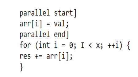
And the last step is to convert CPU codes to GPU kernels. Example converting the loop to the DPCPP kernel

GPU performance tuning
The GPU performance tuning could be done using following three steps.
Tune the kernel size: Offload some iterators outside the kernel. This can help to force to sync the kernel and then change the cache usage. There will be a force sync every x*y*z/N iterator.
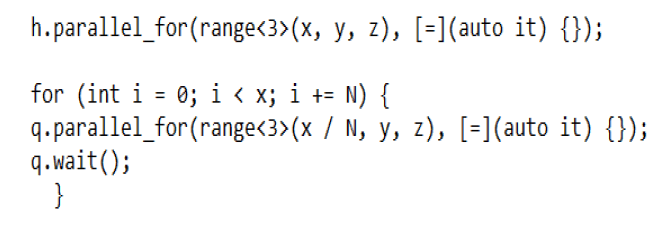
Offload some iterator inside the kernel: This changes the execution order of each work item from parallel to in sequence and then change the cache usage.

Tune the workgroup size: Changing the workgroup size can change the execution order of each work item inside the kernel and then change the cache usage.

Use Intel® VTune profiler: Collect the VTune profiling data with below command.

Case study: BPJ and FPJ code migration and optimizations
BPJ and FPJ description has already been provided in previous section, in this section the authors will start with defining the parameters, associating it with GPU architecture and then diving into optimization details [11]. Few parameter definitions based on Figure 8 of a cone beam back projection geometry.
Note: View: View (angels between source and Y axis) range from 0 to 899; Channels: Column in the project plane; Segments: Row in the project plane; Slice: Image slice range from 0 to 319; Row: Row of the pixel in the image slice range from 0 to 511; Pixel: Column of the pixel in the row range from 0 to 511.
Based on those parameter definitions a two-dimensional project plane for a sample CT dataset provided by Canon Medical will look as shown in Figure 9.
Associating the project plane to memory layout was an important to initiate optimization of the algorithms. Figure 10 shows mapping of project plane to memory layout.
Note: View: View (input params); Segments: Channels is decided by view/row/pixel/slice. For the same view/row/pixel, segments has linear relationship to the slice; Channels: Channels is decided by view/row/pixel. Channels has non-linear relationship to the view/row/pixel.
The volumetric visualization of the same sample dataset that is shown in project plane above (Figure 11).
Similar to memory layout for project plane, a volume memory layout (Figure 12). The image before and after the algorithm were same as shown in Figure 11 and were checked for accuracy.
Note: Row: Row (input params); Pixel: Pixel (input params); Slice: Slice (input params).
BPJ optimizations
This section covers details on optimization of BPJ algorithm and for the rest of this section will focus on various block identification and resulting optimizations that were performed on iterative kernel versions to achieve final performant results.
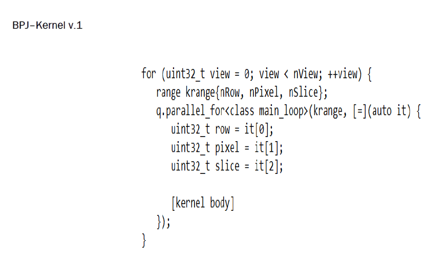
VTune result analysis of Kernel v.1: The points are described the results of the kernel.
• Focused on the main loop kernel which consumes most of the time.
• Big CPU stall: 78.4%*1.7 s. This shows the kernel is memory bound.
• Huge data transaction between the L3$ (L3 cache) and the internal memory.
memory ≥ L3$: 132.6 GB/s*1.7 s=225.42 GB
L3$ ≥ memory: 129.7 GB/s*1.7 s=220.49 GB
BPJ-Kernel v.2: To figure out if the data transaction is due to accessing the input memory or the output memory, input data was moved to the Shared Local Memory (SLM) and profiled again.
VTune result analysis of Kernel v.2: The points are described the significant data transaction.
• After moving input data to SLM, significant data transaction between the L3$ and the internal memory.
memory ≥ L3$: 138.0 GB/s*1.62 s=223.56 GB
L3$ ≥ memory: 135.6 GB/s*1.62 s=219.67 GB
• The memory transaction was due to the below instruction.
FrameBuffRow[slice]+=(vA+((vB-vA)*seg_frac))*InScale*weight;
This instruction read 4 bytes from the memory, updated it and wrote it back to the memory.
Estimate data size: nView*nRow*nPixel*nSlice*4=~300 GB
• For same row/pixel/slice, different view modified the same memory location. The result for each view was saved in the internal memory which caused the huge memory transaction. The conclusion was if this could be moved to the SLM or General Purpose Registers (GRF), it could save lots of memory bandwidth.
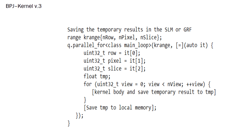
VTune result analysis of Kernel v.3: The points are described the data transaction.
• Data transaction from L3$ to local memory was greatly reduced.
• Data transaction from local memory to L3$ was still high.
• After moving input data to SLM, the data transaction reduced a lot so the data transaction from local memory to L3$ was due to accessing the input memory.
•Checking the layout of the input memory, when the view parameter was changed, the view/ch/seg were also changed, which meant each iterator in the view loop was causing a L3$ refill and then only 4 bytes were read. This caused a great waste of the L3$.
•This called to find a kernel that could better utilize the L3$.
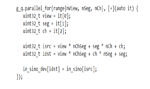
BPJ-Kernel v.4: The seg has linear relationship to the slice if view/row/pixel was fixed. To restructure the input data from data [view][seg][ch] to data [view][ch][seg], accessing the continuous memory from data [view][ch][seg1] to data [view][ch][seg2] was done. Figure 13 shows pictorial representation of this restructuring.
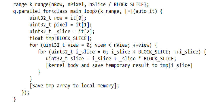
BPJ-Kernel v.5: After restructure, some slice iterators could be moved into the work item so that the work item could access the continuous memory and utilize the L3$ better.
 s
s
• How to choose BLOCK_SLICE
If the BLOCK_SLICE is too small, the L3$ cannot be fully utilized.
If the BLOCK_SLICE is too big, the work item size becomes bigger which was bad for parallel. The usage of SLM or GRF was also increased.
• To compare the effect from BLOCK_SLICE, 3 cases are profiled
Case 1: BLOCK_SLICE=8.
Case 2: BLOCK_SLICE=16.
Case 3: BLOCK_SLICE=32.
VTune result analysis of Kernel v.5: The points are described the BLOCK_SLICE.
• When the BLOCK_SLICE was increased, the GPU idle increased which meant the GPU utilization rate was decreased.
• When the BLOCK_SLICE was increased, the number of memory transaction was decreased.
BPJ-Kernel v.6: With the addition of 5 parameters according to the performance tuning characteristics, the kernel looked like following:
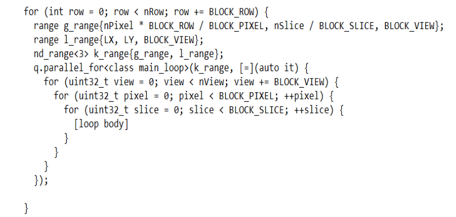
To tune the parameter for BPJ kernel v.6: The points are described the possible value for each of the parameters.
•Exhausted all the possible value for each of the parameters. If it was too slow. The result for each iteration had no relationship so the trend of the result from the previous runs could not be concluded.
•Reinforcement learning faster than exhausting algorithm. Each iteration showed a better or equivalent result to the previous one.
Conclusion of BPJ
With all the kernel optimization and parameter tuning following were the results that the team achieved as shown in Table 2.
| Stage | Results |
|---|---|
| GPU–initial (before tuning) | 40.04 slices/sec |
| GPU–final (after tuning) | 193.06 slices/sec |
Table 2. BPJ results of summary.
Forward Projection (FPJ) optimizations
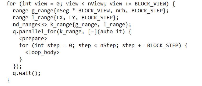
Analysis very similar to BPJ was done for FPJ and similar kernel optimizations for various parameters were applied after looking at the VTune profiler characteristics. Based on the performance tuning characterization, 4 parameters were defined, with those 4 parameters in bold in following kernel.
Conclusion of FPJ
With all the kernel optimization and parameter tuning following were the results that the team achieved as showed in Table 3 for FPJ.
| Stage | Results |
|---|---|
| GPU–initial (before tuning) | 121.354 slices/sec |
| GPU–final (after tuning ) | 300.114 slices/sec |
Table 3. FPJ results of summary.
After both BPJ and FPJ optimizations and improved performance results, the original images as shown in Figures 9 and 11, were regenerated and bit mapping was done to make sure there was no image quality loss.
Real world implications
The authors detail the BPJ and FPJ algorithm optimizations but what makes all the work more meaningful is the realworld implication of the work. With a potential speed up of approximately 5X in BPJ and roughly 2.5X in FPJ, the whole image reconstruction algorithm can have an average speed up of roughly 3.7X. Image reconstruction being the most of compute intensive part of medical imaging workflow, getting a speed-up of more than 3X by just fine tuning existing algorithms and making it vendor neutral, can improve the overall compute efficiency of the workflow and accelerate the time it takes to generate final human readable CT scan images. This acceleration can mean getting CT scan images faster by a few seconds to few minutes, which could not only help with how many patients can be scan per day, thus increasing patient outcome, better utilization of CT scanners at hospitals, but in emergency cases where radiologists need to make conclusions quickly based on imaging data few minutes’ speed-up could potentially make a difference between partial recovery to full recovery. Hence, using technology, both hardware and software to eventually improve patient outcome is critical aspect of the work.
Back projection and forward projection will remain to be critical elements to medical image reconstruction. So, optimizations of these two compute intensive algorithms and migrations to a hardware vendor neutral programming language (DPC++) provides opportunity for programmers and applications developers to speed up their algorithms based on the optimization analysis shared here. The paper also provides to its reader a glimpse into possible CPU and GPU performance numbers using DPC++. This paper focuses on medical image reconstruction algorithms but exact same optimization process can be applied to algorithms in any industry including retail, hospitality, gaming, industrial, financial, automotive and many more, where developers would like to have vendor neutrality of their code in a heterogeneous infrastructure.
The authors plan to continue further optimizing the algorithm and providing test results of optimized vendor neutral code on CPUs, GPUs and FPGAs from multiple vendors, to show a comparative study of the work. The authors, also plan to include AI based speed-up of similar algorithms in the future and if possible, add clinical impact of speed-up in a future study. Additionally, applications of similar optimizations to other reconstruction algorithms in modalities like MR, PET, Xray could be done and applicability to segments outside of healthcare can be studied too.
The work was done as joint collaboration to study unified programming language in medical image reconstruction, running on Intel CPUs and GPUs. Authors have done their best to keep the interpretation from the study unbiased.
BeenishZia: Conceptualization, formal analysis, investigation, methodology, project administration, resources, supervision, writing–original, review and drafting.
Xiang Guo: Formal analysis, investigation, methodology, resources, software, validation, visualization, writing-review and edit.
Yong Tong Chua: Formal analysis, investigation, methodology, project administration, resources, software, validation, writing-review and edit.
Thomas Labno: Conceptualization, formal analysis, data curation, methodology, resources, software, writing–review and edit.
The authors would like to acknowledge several people in Intel Corporation and Canon Medical Research who aided the efforts of the analysis and resulted in this paper.
The datasets and code used in the case study was provided by Canon Medical Research. The test configurations are below.
Test configurations
The points are described the test configurations.
• CPU: 2S Intel® Xeon® Scalable platinum 8360Y.
• GPU: Intel® Data Center GPU flex series 170 (pre-production hardware).
• GPU-driver: Agama-ci-prerelease-335.
• OS: Linux 5.10.54+prerelease 3321, Ubuntu 9.3.0-17 ubuntu1~20.04.
[Google Scholar] [PubMed]