Keywords
|
| Ef f i c i e n c y , Mi c r o c o n t r o l l e r , UART, Compiler, Thermocouples, Serial Peripheral Interface, |
LITERATURE SURVEY
|
| The chart recorders in 19th century replaced the conventional temperature monitoring system used during early days when people used to record temperature manually and plot graph to analyse the system characteristics. S. J. Perez, M.A. Calva and R.Castaneda described a microcontroller based data logging system to record temperature and relative humidity for acoustic measurement applications. Judy Ritchie discussed a comparison of data loggers. According to Petrens et al (2006), result parameters like response time or temperature variation could be determined with classical monitoring and value sensitive monitoring system which were less efficient and slower in operation. Numerous temperature monitoring systems are available like Dickson SM320 display temperature logger, T &D thermo recording monitoring system, FlukeâÃâ¬ÃŸs 1523/1224 reference thermometers, Omega Engineering HH306A Data Logger thermometer etc. These systems have to be connected to computer for data collection. But the system proposed here is equipped with SMS alert service system and improved features. |
INTRODUCTION
|
| This paper introduces a microcontroller-based multichannel temperature monitoring system [6] which is able to store data in a SD Card [9] and sends a SMS to alert the user the exceeded temperature reading set by the user. A keypad is available so the user can set the temperature limit, insert the channel which going to use and the mobile number to send the alert SMS. An LCD displays the temperature reading, as well as the number that is pressed on keypad. |
A. Block Diagram
|
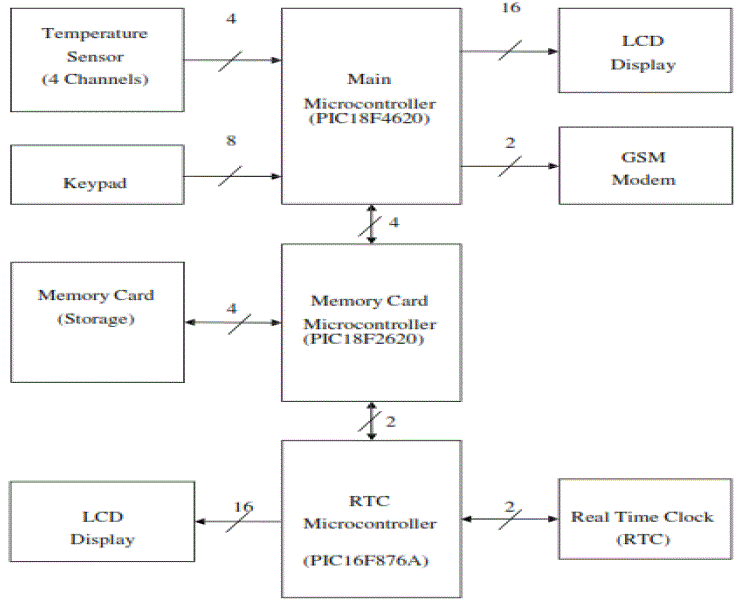
| The block diagram comprises of Temperature Sensors, Keypad, Memory Storage card, LCD display, GSM modem, Real Time Clock and Three microcontrollers as shown in figure A below: |
PCB DESIGN, FABRICATION AND IMPLEMENTATION
|
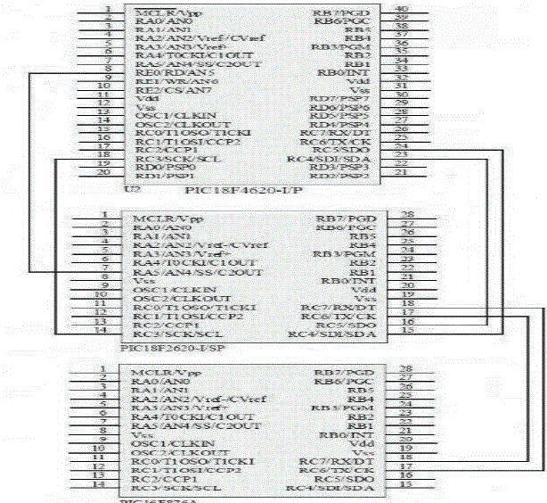
| The PIC18F4620 microcontroller uses 4 pins to interface with the PIC18F2620 microcontroller [7] where the slave select pin of PIC18F2620 microcontroller is connected to chip select pin of the PIC18F4620 microcontroller. SDI from the PIC18F4620 microcontroller is connected to the output data pin, SDO of the PIC16F2620 microcontroller and vice versa. The UART module [4] is used to transfer the data between PIC18F2620 and PIC16F876A microcontrollers. The transmit pin, TX of PIC18F2620 microcontroller is connected to the receive pin, RX of the PIC16F876A microcontroller and vice versa. The present date and time is sent from PIC16F876A to PIC18F2620 microcontrollers to be written into memory card every time the logging interval reached. PIC18F2620 microcontroller is Programmed using mikroC Compiler [11] in mikroC IDE environment into .hex format. The serial clock pin, SCK of both microcontrollers is connected together. It transfers the selected channels, the preset limit, mobile number, and current temperature reading from PIC18F4620 to PIC18F2620 microcontrollers to be logged into the memory card and the system restart. The hardware implementation of three microcontroller has been shown in figure IIIA. |
A. Hardware Implementation of Sensors, LCD and keypad with PIC18F4620 Microcontroller
|
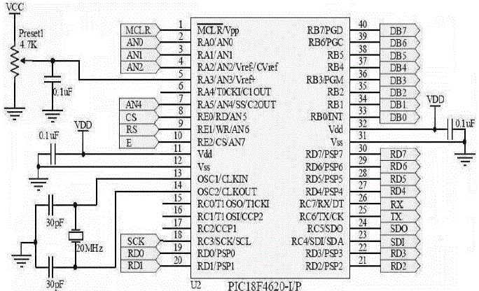
| Figure III.B shows the hardware implementation of PIC18F4620 microcontroller. This microcontroller, acting as a core control unit, communicates with other peripheral devices such as serial EEPROM and shift register and Universal Synchronous Asynchronous Receiver Transmitter (USART/SCI) with 9-bit address detection to communicate with peripheral devices such as analogue to digital or digital to analogue integrated circuits and serial EEPROM. Besides, it is used to convert analogue signal ranging from 0 V to 5 V to a set of binary signals 1 or 0. Meanwhile, the USART module is used to interface with the mobile phone to use the short messaging service feature in the phone. As it serves as the core of the system, it connects most of the peripheral devices of the system such as temperature sensors, keypad, mobile phone, and liquid crystal display (LCD). |
B. Memory Card Microcontroller PIC18F2620 and RTC Microcontroller PIC16F876A
|
| PIC18F2620 microcontroller, Programmed using mikroC Compiler in mikroC IDE environment, is used to write data into the SD card. Its 28 pins consist of 32K× 14 words of Flash Program Memory, 3968 × 8 bytes of Data Memory (RAM), and 3 input output ports. PIC16F876A, Programmed [8] using MPLAB IDE environment and compiled using HI-TECH C Compiler into .hex file, is selected to interface with the DS1307 RTC chip and displays the date and time using LCD screen. The RTC chip is connected using I2C Master mode in the MSSP module where SDA and SCL pins are used. Information such as current date and time are transferred from the chip into the microcontroller. The microcontroller is then connected to the PIC18F2620 to send the current date and time using USART module in Transmit mode. PIC16F876A and PIC18F2620 microcontrollers are connected with each other using TX and RX pins, where date and time are transferred to be written into the SD card. |
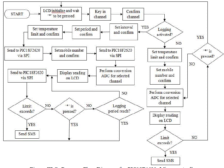
| The overall flow diagram elaborates the initialization such as LCD initialization and SPI [2] initialization and then, the system checks for the presence of SD Card. When a SD Card is detected, it will prompt the information [10] such as logging interval, logging period, temperature preset value and mobile number to be transferred from PIC18F4620 to PIC18F2620 microcontrollers and written into the SD Card. Meanwhile, the date and time will be transferred from PIC16F876A to PIC18F2620 microcontrollers. |
C. SD Card and Liquid Crystal Display (LCD) Implementation
|
| Interfacing between an SD/MMC Card module and the microcontroller uses four input output lines include the three SPI bus lines (SCK, SDO and SDI), and chip select line. High Level translation for the microcontroller SDO, SCK and CS outputs is implemented with simple resistor voltage dividers in the SD Card module. The SPI is initialized before the presence of the SD Card is checked which then creates a file inside the memory card with predefined format file name. The data is then written into the file and it may continue to append the same file if more data is to be written according to the defined logging interval. A Hitachi 44780-Based LCD with high quality 16 character by 2 line intelligent display module, which works with almost any microcontroller is used here. 2 lines are used instead of 1 line display as the project is built on minimum 4 channels. Therefore, the LCD will display 2 channels at one time. Besides that, the JHD162A LCD is built with 5×7 dot matrix character with cursor and 4×4 matrix keypad. |
EXPERIMENTAL RESULTS AND CONCLUSION
|
A. Memory Card Testing
|
| Testing on SPI connection between SD Card slot and microcontroller is carried out. When the SD Card is detected, the 18F2620 starts to initialize the SPI and the SD Card. Then, a file name is created by using date and month which are transferred from PIC16F876A via UART module with the d e f i n e d date and time properties of the .When the „*âÃâ¬ÃŸ key is pressed during temperature reading operation, observation shows that system is restarted and channel selection menu is displayed. After the file is created, a “CIT TEMP MONITORING SYSTEM” file header is written into it. The preset limit and mobile number is retrieved from PIC18F4620 to PIC18F2620 microcontroller to be logged into the memory card. |
B. Experimental Readings
|
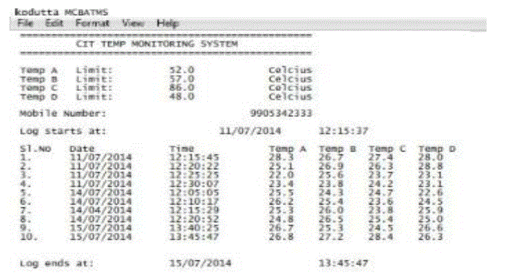
| Table III.A shows the readings obtained from the four channels at interval of 5 minutes at air at environment temperatures. The readings of the channels are compared with the readings of temperatures obtained from the standard temperature indications obtained from the thermometer. The same result has been displayed using excel sheet and printed through note-pad in figure 3a |
C. Conclusion
|
| The microcontroller based multichannel ( four channels) temperature monitoring system has been successfully constructed and the whole system functions successfully. Every monitoring system used earlier needed to be connected to the computer for data collection. But the proposed system designed here is capable of sending SMS alert to the user and system has been successfully implemented with improved features. The device is able to measure the temperature range from 0 to 310 °C using K-type thermocouple and from 0 to 230 °C for LM35DZ temperature sensor. Both sensors convert the output voltage from temperature sensor to digital signal via ADC. A short message is sent out via GSM modem when the preset temperature exceeds the limit. RTC is also successfully implemented and the data and time is sent to PIC18F2620 from 16F876A microcontrollers via UART. The results obtained from the measurement have shown that the system perform well under all the conditions. |
FUTURE SCOPE
|
| system performance can be improved by choosing microcontroller chip with better features having more memory capacity, operating speed, instruction cycle period etc. This system can be connected to satellite terminal to enable the remote collection of recorded data or alarming of certain parameters. The new system may be designed to email information based upon a regular schedule based upon alarms. |
Tables at a glance
|
 |
| Table 1 |
|
Figures at a glance
|
 |
 |
 |
| Figure 1 |
Figure 2 |
Figure 3 |
 |
 |
 |
| Figure 4 |
Figure 5 |
Figure 6 |
|
References
|
- A guide to data logging tutorial by Judy Ritchie, Copyright 1996-2003 by Onset Computer Corporation.
- A.K. Oudjida et ai, FPGA Implementation of I2C & SPI protocols A Comparative Study". Proceedings of the 16th edition of the IEEEInternational Conference on Electronics Circuits and Systems ICECS, pp.507, 2011
- Daniel D. Pollock, Thermocouples: Theory and Properties.
- Fang Yi-Yuan, Chen Xue , Design and simulation of UART serial communication module based on VHDL , IEEE Explore, may 2011.
- F. Vahid and T. Givargis, Embedded System Design: A Unified Hardware/Software Introduction, John Wiley & Sons
- Ibrahim, D. (2008). Advanced PIC Microcontroller Projects in C: From USB to RTOS with the PIC18F Series. Burlington: Elsevier Ltd.
- Julio Sanchez and Maria P. Canton, Microcontroller Programming: The Microchip PIC
- Microchip. (2011). MPLAB C Compiler for PIC18 MCUs. Retrieved May23, 2014,from
- MicroDAQ.com. (2011). T and D Thermo Recorder Data Logger. Retrieved February17, 2014,
- S. J. Perez, M. A. Calva, R. Castaneda, “A microcontroller based data logging System” 510, Dec 13-16 2009.
- Ted Van Sickle, Programming Microcontrollers in C.
- Thomas W. Kerlin, Practical Thermocouple Thermometry.
|