Study is presented into the performance of Fast Fourier Transform (FFT) and Discrete Wavelet Transform (DWT) and MIMO-DWT with transmit beamforming. Feedback loop has been used between the equalizer at the transmitter to the receiver which provided the channel state information which was then used to construct a steering matrix for the transmission sequence such that the received signals at the transmitter can be combined constructively in order to provide a reliable and improved system for next generation wireless systems. As convolution in time domain equals multiplication in frequency domain no such counterpart exist for the symbols in space, means linear convolution and Intersymbol Interference (ISI) generation so both zero forcing (ZF) and minimum mean squared error (MMSE) equalizations have been employed. The results show superior performance improvement and in addition allow keeping the processing, power and implementation cost at the transmitter which has less constraints and the results also show that both equalization algorithms perform alike in wavelets and the ISI is spread equally between different wavelet domains.
Keywords |
| Multiple-Inputs Multiple-Outputs (MIMO), Beamforming, Discrete Wavelet Transform (DWT), Zero
Forcing (ZF), Intersymbol Interference (ISI), Minimum Mean Squared Error (MMSE) |
| |
| |
INTRODUCTION |
| In the world of communication any problem within the communication system is usually divided into two main parts,
i.e. source coding and channel coding. In a number of ways it can be assumed that these techniques are interrelated
which provides us with some very important algorithms and techniques that can then be employed to solve these
problems. When the word source coding is used it usually refers to the idea that some type of discrete representation of
the data is sorted so as to reduce the redundancy that is present in the transmission sequence, but on the other hand the
channel coding defines the distortion that is brought into the discrete transmission scheme, in order to minimize the
channels distorting effects on the symbols. There are many different techniques present in the literature for channel
coding but the best performance is only achieved if the channel through which the data stream has to travel is known
and this information can be attained from the equalizer at the receiver by using a closed loop to the transmitter. |
| With the continuous increase in the demand of high performance systems for multiple classes of traffic researchers
have proposed that replacing the conventional Fourier based OFDM [1-6] system with the filter bank based multirate
wavelet transform can provide some extra advantages like that of multiresolution analysis, which allows the signal to
be studied in space, or time – frequency domain, another major contribution of the wavelet transform is that it is more
spectrally efficient because the input data stream is divided into approximate and detailed coefficients providing the
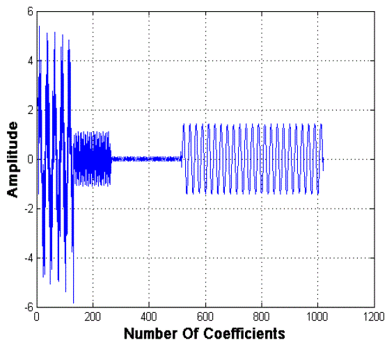
land and groves of the transmission sequence as shown in Fig. 1 for a sum of sinusoidal waves. Now this concept
closely follows the OFDM transmission structure where the transmitted sequence is divided into a number of sub
carriers but they are orthogonal to each other, and the orthogonality is sometimes severely damaged by the multipath
[7] which will make these subcarriers overlap causing ICI and making it hard for the equalizer to decide what was the
real transmission sequence, which then requires for the guard band to be inserted to separate the symbols in time so
they do not overlap making the scheme suitable for multipath transmission. Then there is another problem with the FFT
and that is of leakage causing inter symbol interference, but in the case of wavelets which provides groves as the
approximate coefficients and lands as detailed just like in a rifling process even if the grove is damaged it can still be
easily differentiated from the land and no guard band insertion is required and the leakage in wavelets is almost negligible and the main energy is concentrated in the main lobe which make this transform a perfect choice for any type
of unreliable channels. Symbol orthogonality is maintained using the perfect reconstruction quadrature mirror filter
bank which consist of half band low pass and half band high pass filters on one end of the transmission system and the
conjugate mirrored filters on the other end. |
| This transform also has the advantage that the signal is divided into its individual components and every component
is assigned a different frequency band in the frequency spectrum which results in reduced computational complexity as
compared to the division into individual sinusoids as in Fourier transform from O(Nlog2N) to O(N) [8]. |
| The bases functions for wavelet transform can be localized in space using the multi-resolution analysis [9] and the
harmonics can be very easily distinguished. |
| Another way of increasing the reliability and to increase the transmitted or received data rates is to employ Multiple
Input Multiple Output systems as they can be used to take advantage of the spatial diversity or time diversity by
creating multiple channels in space without using any additional bandwidth [10]. The main reason behind the success
of the MIMO systems is the same that they are more spectrally efficient and less transmission power is required to
match a given throughput at a certain BER level as compared to the SISO systems [11]. In [12] WPM Multicode
CDMA system performance was compared against the conventional Multicode CDMA system. In [13] again
performance of WPM-MIMO in AWGN was studied and it was shown that the WMCM systems perform better and
MIMO systems enhance system performance in AWGN channel. |
| A new wavelet based system has been presented that uses the time-frequency localization of the wavelet transform
and also the transmit diversity technique in conjunction with beamforming to achieve high rate data transmission and
reliability for the next generation wireless systems (NGWS). The performance of two different equalization techniques
has been considered as there is no convolution counterpart available for the symbols present in wavelet domain which
can give rise to ISI. The study was done using Rayleigh multipath fading channel and AWGN. |
| The rest of this paper is divided as follows. Section II introduces the concept of wavelet analysis and perfect
reconstruction, Section III details the system model, Section IV deals with the error probability, followed by the
discussion on the simulation results in Section V and the conclusion is presented in section VI. |
II. INTRODUCTION TO WAVELET ANALYSIS |
| Signals can be decomposed into their constituent components each corresponding to different scales each within a
different frequency range using the wavelets transform allowing the signal to be studied much more efficiently by
changing the scale of the frequency for a particular component of interest. |
| Wavelets as the name suggests are wave like oscillations which quickly decay and are used to represent the mother
function or the mother wavelet from which the daughter wavelets are generated and are in reality just the scaled and
translated replicas [10]. There are infinite sets of basis fuctions available for the wavelets and any one of them can be
employed for the signal study making it different from any other known method of signal analysis. |
| The continuous wavelet transform can be mathematically defined as [10]: |
 |
| where "x" represents the scaling factor, "z" is the shifting parameter and “ψx,z t " denotes the mother wavelet. In its
continuous form the data carries redundant information and the transform will require extensive analytical calculation
for which we then sought the discrete representation in order to be able to devise a viable inverse transform function for
the practical employability of the technique. |
 |
 |
 |
| The discretized mother wavelet will be of the form: |
 |
| The product of any random signal s[n] with the scaling and wavelet function provides us with the desired DWT [10]
as shown here after. |
 |
| Where, φ t represents the scaling function and ψ(t) is the wavelet function. These functions are discretized values
at a (a = 1,2 … ,m) and at translation b (1,2 … . , t). The filters of the perfect reconstruction quadrature mirror filter
bank (PR-QMF) that are used to implement the DWT consisting of half band high pass g(b) and half band low pass
h(b) filters in a multicarrier modulation system follow the relationship as in (7) if the impulse response of one filter is
known the rest can easily be calculated using (7); |
 |
| And these filters must satisfy the condition |
 |
| The resultant approximate and detailed coefficients obtained for the DWT are of the form; |
 |
| The shifting and translation of the wavelet signal causes a delay within composite symbols by a factor „ α‟ in
accordance to the z-transform relation (X z = n x m z−α, where z−α = e−jαw) and requires adjacent matched filters
to perfectly reconstruct the signal. This condition can be represented mathematically as [14]. |
 |
 |
III. SYSTEM MODEL |
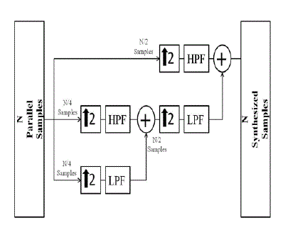
| A general representation of the system model is presented in the Fig 1., where the discretized and modulated bit
stream is first converted from serial to parallel and then passed through the synthesis filter bank. There is a trade off
present between the levels of synthesis and decomposition that are employed and the system latency which can be
optimized according to the application requirement or the channel requirements. Before the parallel symbol streams
pass through the filters within the filter bank they are upconverted which increases the signal resolution in order to
provide a very detailed description of the signal and to provide a more accurate approximation. After the required N level of synthesizing the synthesized wavelet symbol is then propagated through the multipath fading channel using the
transmission scheme. At the receiver the received signal is equalized to remove any unwanted channel effects and then
passed to the analysis filter bank where it is decomposed and down sampled and the channel state information is also
sent to the transmitter to adjust the next transmission sequence according to the channel conditions. |
| A. DWT in Transmitter |
| In a multicarrier system unlike image processing the inverse wavelet transform is applied at the transmitter in order
to synthesize the transmission sequence as shown in Fig. 2a., using the PRQMF. This convolution between the symbols
and the filters can be mathematically described as; |
 |
| The process of IDWT is also referred to as a Synthesis Process. This synthesized signal then propagates through the
Rayleigh multipath fading channel in the presence of noise. For greater understanding of the process of convolution of
the wavelet symbols and the channel please refer to authors [1]. |
| B. DWT signal in Multipath Rayleigh Channel and AWGN |
| When the signal is propagated through the channel it suffers the phase and amplitude distortions due to fading, either
its flat fading or frequency selective fading. In addition to these changes in a multipath environment reflection and
diffraction effects cause many multiple time delayed copies of the signal to arrive at the receiver which if combined
destructively will lose all the information. The effects caused by the multipath channel can be summarized in a
mathematical form as; |
 |
| The amplitude change and the time delay of the signals travelling through the channel in (12) are represented by
am t, τ , and τm is the phase shift for the mth multipath at the time instance t. Multipath summation limits are from 1 to
M with Dirac delta δ • . |
| C. DWT in Receiver |
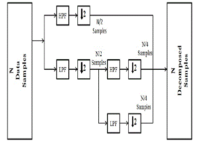
| The received signal after equalization is passed through the conjugate LPF h*(-b) and HPF g*(-b). The signal gets
decomposed within analysis filter bank into its constituent approximate and detailed coefficients and then
downsampled to further reduce the redundancy by a factor of 2. The process is repeated again until the desired N data
streams are successfully retrieved. These parallel streams are then converted back to the serial using serial to parallel
converter and then demapped. |
IV. ERROR PROBABILITY |
| The instantaneous error probability in the presence of AWGN for lucid detection can be stated in the form of
mathematical expression as: |
 |
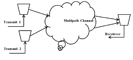
| In order to improve instantaneous error probability beamforming can be applied which will align the phases of two
different incoming signals at the receiver in order for constructive combination of both the incoming signal streams in
order to achieve high diversity gain, because otherwise the signals transmitted through the different antenna elements
will travel through two separate Rayleigh multipath channel and can only provide SISO like performance due to the
phase difference of the received waveforms at the receiver. Mathematically the implementation of this technique can be
realized as; |
| If „s‟ is the transmitted symbol, „h‟ is the channel impulse response then; |
 |
| The addition of the AWGN by the channel is represented as n. For a transmit diversity system having two transmit
antennas (14) can be modified as where instead of one we have two separate channels |
 |
| Let us assume that the channel estimator feedback loop has provided us with the CSI and the channel phases are ejφ1 and ejφ2 respectively. Them (15) can be further modified to add this information and the steering matrix can be
calculated. |
 |
| As a result of the channel knowledge and the steering matrix we can successfully constructively combine both
incoming signal streams to achieve maximum diversity gain. |
V. SIMULATION RESULTS AND DISCUSSION |
| All the simulations have been carried out using Monte Carlo simulations. Table (1) summarizes the basic parameters
that have been used for the experiment. |
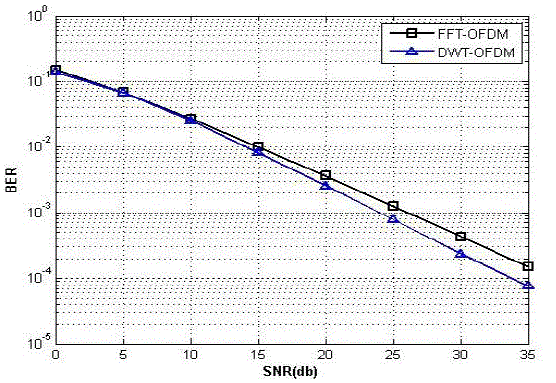
| The first part of the performance study was done to verify the theory that states that wavelet transform will outperform
the conventional OFDM system as it is an industry standard and widely accepted but as can be seen in Fig. 4 that at the
BER around 10-4 region discrete wavelet transform is providing about a 3dB gain out of which 1dB can be associated to
the removal of CP making the transform spectrally efficient and another 2dB gain which proves that the idea of using
filter banks based waveforms is quite attractive as the coefficients carrying the information has the information divided
in such a way between approximation and detail parts that even after the degrading effects of the multipath channel and
the ISI caused by the linear convolution of the synthesized wavelet symbol and channel the data was still recovered
with less errors. |
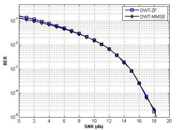
| The next important question that comes to mind is that can this gain be increased by utilizing some other type of
equalization method, but as can be seen in Fig. 5 that both the ZF and MMSE equalization algorithms performed alike,
ZF gives rise to extra noise and MMSE has extra ISI which is spread on different wavelet domains that is why
equalization of wavelets is still challenging, even though these two algorithms show performance difference when
employed in FFT-OFDM systems. |
| In order to further enhance the capability of the system MIMO was employed but in a special way by incorporating the
forward error correction by making use of the CSI and the results showed an outstanding performance difference,
between just 2 transmit 1 receive antenna‟s and when the signal streams are steered using the matrix calculated
according to the channel phase knowledge as can be seen in Fig. 5. Another important thing to note here is that the
performance of Biorthogonal and Reverse Biorthogonal differs even within the same comparison parameters because of
different reconstruction properties, for more detail on the subject of wavelets user is referred to [9]. |
VI. CONCLUSION |
| It can be concluded from the results produced that wavelet transform is indeed a better scheme for the multicarrier
modulated systems and also for any type of unreliable channels because of its effectiveness in multipath environments.
It is also concluded that the guard band saving which typically depend on the system design and wastes bandwidth can
be saved using wavelet transform. Furthermore the proposed use of the FEC in the DWT-MIMO systems showed
remarkable performance improvement and gain of about 18dB as compared to a simple two transmit and one receive
antenna systems. Another thing that was seen in the results is that not all wavelet families perform alike which can
form an interesting future contribution to get insight into the wavelet families and their behaviour and the optimal
decomposition level and filter order. |
ACKNOWLEDGMENT |
| This work has been performed in the framework of ARTEMOS project under work programme ENIAC JU 2010
and FCT (Fundação para a Ciência e Tecnologia). |
| The authors would also like to thank the support from Datong Plc. UK, under the KTP project No. 008734 with
Bradford University. |
|
Tables at a glance |
 |
| Table 1 |
|
Figures at a glance |
 |
 |
 |
| Figure 1 |
Figure 2 |
Figure 3 |
 |
 |
 |
| Figure 4 |
Figure 5 |
Figure 6 |
|
| |
References |
- R. Asif, R.A. Abd-Alhameed, O.O.Anoh and Y.A.S. Dama, Performance Evaluation Of FFT-OFDM and DWT-OFDM for multicarriercommunications systems using time domain zero forcing equalization, International journal of Computer Applications, Foundation of ComputerScience, NY, USA, Vol. 51, No. 4, pp- 34-38, August 2012.
- A.N. Akansu and L. Xueming, A comparative performance evaluation of DMT (OFDM) and DWMT (DSBMT) based DSL communicationssystems for single and multitone Interference, IEEE International Conference on Acoustics, Speech and Signal Processing, Seattle, WA, Vo. 6, pp.3269 - 3272, 1998.
- F.Farrukh, S.Baig, and M.J. Mughal, Performance comparison of DFT-OFDM and Wavelet-OFDM with zero-forcing equalizer for FIR channelequalization, International Conference of Electrical Engineering, ICEE, pp. 1- 5, 2007.
- C. Van Bouwel, J. Potemans, S. Schepers, B. Nauwelaers and A.Van de Capelle, "Wavelet Packet Based Multicarrier Modulation", Symposiumon Communications and Vehicular Technology, Leuven, pp. 131-138. , 2000.
- B.G. Negash and H. Nikookar, "Wavelet based OFDM for wireless channels", Vehicular Technology Conference2001,VTC 2001, VTC 2001Spring. Spring, 2001, IEEEVTS, Vol. 53, No 1, pp. 688-691 , 2001
- Anoh, O.O.; Ali, N.T.; Abd-Alhameed, R.; Jones, S.M.R.; Dama, Y.A.S., On the performance of DWT and WPT modulationformulticarrier systems, IEEE 17th International Workshop on Computer Aided Modeling and Design of Communication Links and Networks(CAMAD), pp. 348-352, 2012.
- J.G. Proakis, Digital Communications, McGraw-Hill, 1995.
- C. S. Burrus, R. A. Gopinath and H. Guo, âÃâ¬ÃÅIntroduction to Wavelets and Wavelet Transforms-A Primer, Prentice-Hall, New Jersey, USA, 1998.
- Daubechies, Ten Lectures on Wavelets, 2nd Edition. Philadelphia, PA, USA. CBMS-NSF-Regional Conference Series on AppliedMathematics, 1992.
- J.G. Andrews, A. Ghosh, R. Muhamed, Fundametals of Wimaxx understanding broadband wireless networking, Prentice Hall, PearsonEducationInc, NJ, USA, 2007.
- S.J. Kim, R. E. Cagley and R. A. Iltis, Spectrally Efficient Communication for Wireless Sensor Networks Using a Cooperative MIMOTechnique, Wirelesss Networks, Vol. 13, No. 3, pp. 397-407, 2007.
- Maryam M, Okechukwu C, Diversity Performance of a Wavelet-Packet-Based Multicarrier Multicode CDMA Communication System, IEEETransactions on Vehicular Technology, Vol. 57, No. 2, March 2008.
- Lei Yan, Wavelet Packet Multicarrier System Based on MIMO Antenna in AWGN, International conference on Neural Networks and SignalProcessing, pp. 233-237, 2008.
- M. Vetterli and C. Herley, âÃâ¬ÃÅWavelets And Filter Banks: Theory And Design,âÃâ¬Ã IEEE Transactions on Signal Processing, Vol. 40, No. 9, pp. 2207âÃâ¬Ãâ 2231, Sept.1992,
- Manglani, M. J. and Bell, Amy E., âÃâ¬ÃÅWavelet Modulation Performance over AWGN and Rayleigh Fading Channel.âÃâ¬Ã IEEE MilitaryCommunications Conference. MILCOM 2001,pp. 845 âÃâ¬Ãâ 849, 2001.
|