Keywords
|
| Miniaturization, Metamaterial, Microstrip Patch Antenna, Double Negative Property. |
INTRODUCTION
|
| Microstrip Patch Antenna has been very popular due to their small size , light weight, low profile, less cost. Apart from these advantages they also have various disadvantages like narrow band width, less gain etc. It has always been desired to reduce the size of the antenna while keeping the remaining parameters same, this helps us using the small antenna at lower frequencies. Here “H shaped inter connected split ring” Meta material structures is used to reduce the size of the Microstrip patch Antenna. Metamaterials were first discussed by Viselago in 1967. Metamaterial are not available in nature. They are man made structures that show negative permittivity and negative permeability. J B Pendry in 1999 first proposed his design of thin wire (TW) and split ring resonator(SRR).Dr Smith combined the two structures and created the first Metamaterial structure. |
II. LITERATURE SURVEY
|
| The size of the Microstrip patch antennas at UHF is very large as its length is inversely proportional to frequency. Hence to reduce the size of the antenna various methods were used like using substrates of higher dielectric constant but this also reduces the bandwidth and gain considerably. Other methods of reducing size is shorted Microstrip patch antenna but here also efficiency, gain, cross polarization levels are not as good. Metamaterials are structures that are used to enhance the properties of Microstrip patch antennas, like directivity, size, bandwidth etc. Work has been done where these properties of Microstrip patch antenna has been enhanced. In this paper we have reduced the size of the Microstrip patch antenna while increasing the directivity. |
III. DESIGN PROCEDURE, FORMULATION OF MICROSTRIP PATCH ANTENNA.
|
DESIGN FORMULAE:
|
| (1) Calculation of Width: |
 |
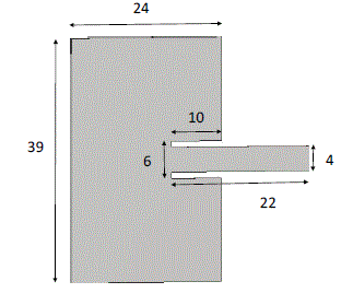
| The parameters of the rectangular Microstrip patch antenna are calculated from the above given formula are L=39mm, W=24mm, cut width=6mm, cut depth=9mm, Length of the transmission line=22mm, width of the feed line=4mm. The rectangular Microstrip patch antenna as shown in Fig1 is designed on dielectric substrate having dielectric constant =4.3 and height from the ground plane d=1.6mm. |
IV. SIMULATION AND RESULTS
|
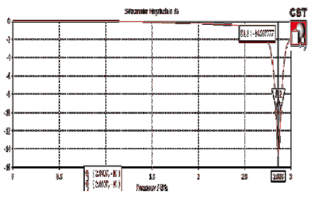
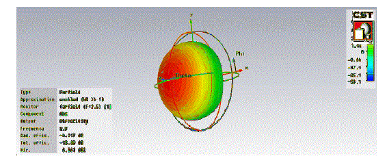
| Here we have first simulated the above antenna using CST software its results of return loss and radiation pattern are as shown in figure 2 and figure 3. |
| The return loss characteristic of RMPA at 2.865 GHZ is shown below in Figure2 showing return loss of -14.99dB. |
| Figure3 shows the3D radiation pattern of the RMPA showing directivity of 6.861dBi. |
A. Nicolson-Ross-Weir (NRW) Approach:
|
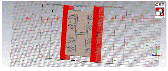
| The proposed structure is placed between the two wave guide ports at the left and right of the X-Axis (as shown in figure 4) in order to calculate the S11 and S21 parameters so as to prove that the proposed structure possesses Double Negative Meta material properties. In figure 4, Y-Plane was defined as Perfect Electric Boundary (PEB) and Z-Plane was defined as the Perfect Magnetic Boundary (PMB). Subsequently, the wave was excited from the negative Y-Axis (Port 1) towards the positive Y-axis (Port 2). This setup mimicked the waveguide and it was suitable to calculate the SParameters for the extraction of the effective parameters later on. |
| B. Equations used for calculating permittivity and permeability using NRW approach:- |
 |
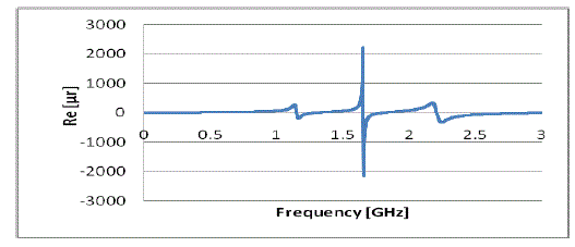
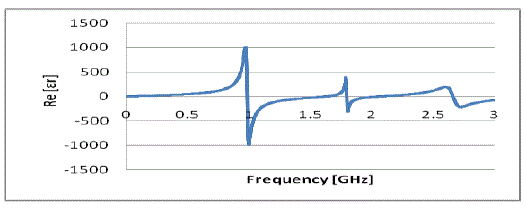
| Figure 5 and 6 shows the negative value of permeability and permittivity at the operating frequency. |
| The table generated for Permeability and Permittivity using Microsoft Excel software was to large hence few important values for the frequency range 2.8529 GHz to 2.871 GHZ is shown in Table 1 and Table 2. After verifying the negative properties of Permeability and Permittivity the proposed structure was designed and placed at a height of 3.2mm from the ground plane. |
C. Designing and simulation of “H Shaped interconnected” split ring Metamaterial antenna.
|
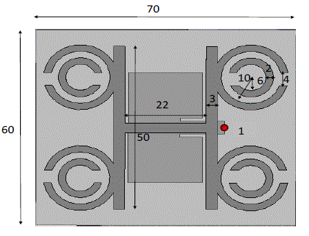
| The” H shaped inter connected split ring” shaped metamaterial structure is placed above the patch antenna at a height of 3.2mm from the ground plane in order to study its influence, and the results are compared with those of the patch antenna alone. |
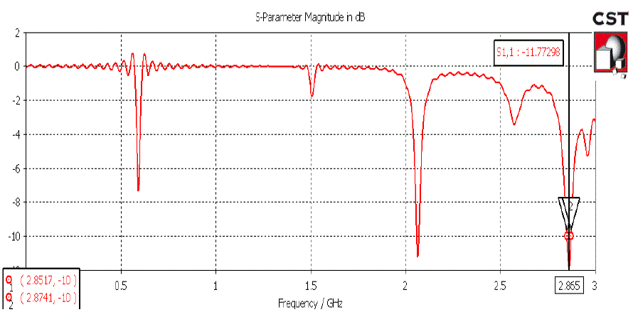
| Figure 7 shows RMPA loaded with “ H shaped inter connected split ring” shaped metamaterial structure at a height of 3.2mm from the ground plane. Dimensions of the antenna are shown in the figure 7. The proposed metamaterial structure reduces the antenna size while increasing the directivity. Figure 8 shows the return loss at 2.865 GHz . |
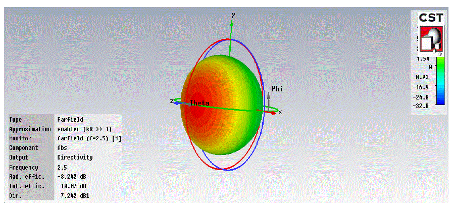
| By using the proposed metamaterial structure along with the patch antenna at a height of 3.2mm from the ground plane, increases the directivity by 1.068dBi and the total efficiency is also improved as shown in figure 9. |
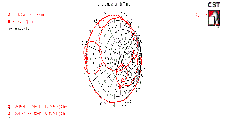
| Smith chart in figure 10 shows the impedance matching of the proposed antenna with the co-axial cable of 50Ω. |
| By the simulated results, it has been observed that the overall size of the RMPA is reduced by 27% when incorporated with the proposed metamaterial structure at a height of 3.2mm from ground plane. Table 3 shows the overall dimensional comparison of RMPA alone and RMPA with the “H shaped inter connected split ring” shaped metamaterial structure.It shows that length is reduced from 39mm to 34mm,similarly other parameters are also reduced which reduces the overall area by 27%. |
D. Fabrication and Measurement of the designed antenna
|
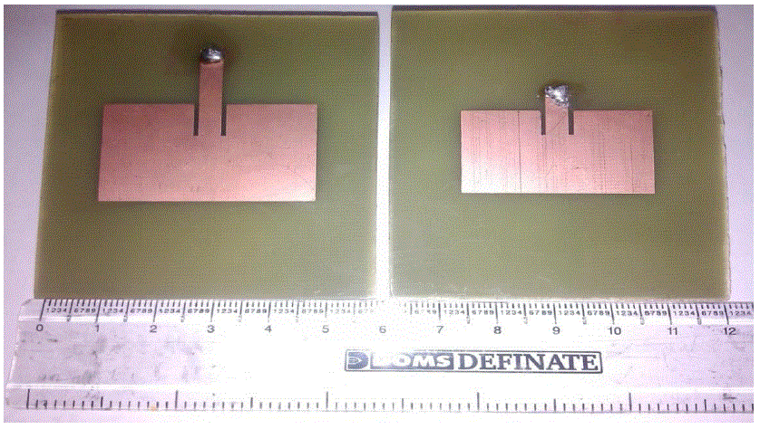
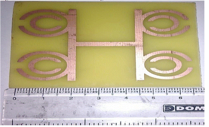
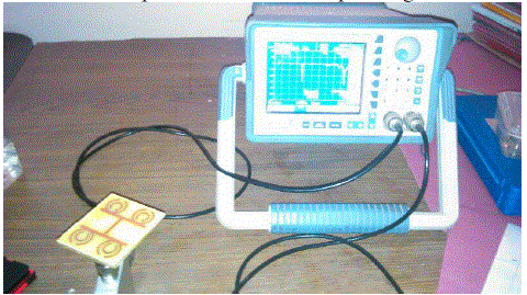
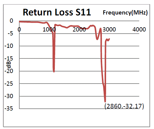
| First using CST software we designed the antennas then the same antennas were fabricated as shown in figure 11. In this figure RHS antenna is the original antenna while LHS is the modified antenna which is used with the metamaterial antenna. Metamaterial antenna the “H shaped interconnected antenna” is as shown in figure 12. This metamaterial antenna is kept over the modified antenna and the results of return loss were calculated using Spectrum Analyser as shown in figure 13. The return loss of the tested antennas is shown in figure 14. The fabricated antenna has S11 -32.17 dB at 2.865 GHz. This result is similar to what we have achieved with CST software. |
V. RESULTS AND DISCUSSION
|
| Advantages of using H shaped interconnected split ring Metamaterial with RMPA is explored . Proposed metamaterial structure reduces the average area of the antenna by 27% and increases the directivity of the antenna by 1.06dBi.As shown in Table 3 the size of the original antenna is reduced. Figure 9 shows that the modified antenna has greater directivity and figure 14 shows that this antenna offers good return loss at the same frequency as shown by the original antenna |
VI. CONCLUSION
|
| Thus in this paper we have investigated the use of matamaterial structure to reduce the size of the Microstrip patch antenna while increasing its directivity. |
| |
Tables at a glance
|
|
|
Figures at a glance
|
 |
 |
 |
 |
 |
| Figure 1 |
Figure 2 |
Figure 3 |
Figure 4 |
Figure 5 |
 |
 |
 |
 |
 |
| Figure 6 |
Figure 7 |
Figure 8 |
Figure 9 |
Figure 10 |
 |
 |
 |
 |
| Figure 11 |
Figure 12 |
Figure 13 |
Figure 14 |
|
| |
References
|
- V.G.Veselago “The electrodynamics of substances with simultaneously negative value e and µ” Sov. Phys. Uspekekhy. 10(4), 509-514,1968
- Constantine A. Balanis, Antenna Theory and Design. John Wiley & Sons, Inc. 1997.
- J.B. Pendry, A.J. Holden, D.J. Robbins, W.J. Stewart, “Magnetism from conductors and enhanced nonlinear phenomena” IEEE Trans.Micro Tech. vol. 47 no. 11, pp. 2075-2081, Nov. 1999.
- D.R. Smith, W.J. Padilla, D.C. Vier, et al, Composite medium with simultaneously negative permeability and permittivity, Phys Rev Lett 84,4184-4187, May 2000.
- J.B. Pendry, Negative refraction males a perfect lens, Phys Rev Lett, 85, 3966-396, 2000.
- David M. Pozar, “Microwave Engineering”, 3rd Edition, John Wiley & Sons, 2004.
- NadarEngheta, Richard W. Ziolkowski, “Metamaterial Physics & Engineering Explorations”, July 11, 2006.
- Ahmad A. Sulaiman, Ahmad S. Nasaruddin, “Bandwidth Enhancement in patch antenna by metamaterial substrate”, European Journal ofscientific research, 2010.
- Huda A. Mazid, Mohammad Kamal A. Rahim, ThelasaMasri, “Left-handed metamaterial design for Microstrip antenna application”, IEEEInternational RF and Microwave conference, 2008.
- G. Lovat, P. Burghignoli, F. Capolino, and D.R. Jackson. R.W. Ziolkowski, “Combinations of low/high permittivity and/or permeabilitysubstrates for highly directive planar metamaterial antennas”. IET Microw. Antennas Propag. 1.177 (2007).
- S. Pvo. S. – M. Han. J. – W. Baik, W. – S. Yoon. And Y. – S. Kim. “Offset-fed metamaterial antenna for radiation mode generation withefficiency improvement”. IET Microw. Antennas Propag. 4.1481 (2010).
- H.A. Majid, M.K.A. Rahim and T. Masri, Microstrip Antenna gain enhancement using left-handed metamaterial structure, progress inElectromagnetic Research M. Vol. 8, 235-247, 2009.
- C.M. Krowne, “Low loss guide wave propagation in a left-handed Microstrip structure using dispersive split ring-rod combinationmetamaterial”, IET Microw. Antennas Propag. 1.887 (2007).
- J. Lee and S. Lim, “Bandwidth-enhancement and polarization in sensitive metamaterial absorber using double resonance”, Electron Lett. 47.8 (2011).
- Zhu, C., Ma, J.J., Li, L., and Liang, C.H.: “Multiresonantmetamaterial based on asymmetric triangular electromagnetic resonators”, IEEEAntennasWirel. Propag. Lett.”. 2010, 9, pp. 99 – 102.
- D. Kim and M. Kim, “Narrow-beamwidth T-shaped monopole antenna fabricated with metamaterial wires”, Electron Lett. 44, 179 (2008).
- C. Zhu, J. – J. Ma, L. Li. and C. – H. Liang, “Low-loss triangular left and right-handed metamaterials”, Electron Lett. 6 Volume 47, Issue 1,p.12– 14 doi: 10.1049/el. 2010.2856, January 2011.
- FilibertoBilotti, Senior Member, IEEE, Andrea Alu, Member, IEEE, and LucioVegni, Member IEEE, “Design of MiniaturizedMetamaterial Patch Antennas with µ - Loading”, IEEE Transactions on Antennas and Propagation, Vol. 56, No. 6, June 2008.
|