ISSN ONLINE(2319-8753)PRINT(2347-6710)
ISSN ONLINE(2319-8753)PRINT(2347-6710)
J.Arul sheeba 1, B.Pushpavanam 2
|
| Related article at Pubmed, Scholar Google |
Visit for more related articles at International Journal of Innovative Research in Science, Engineering and Technology
A feedback network for forward converter that automatically reduces the current flowing through the opto-coupler under no-load condition is presented in this paper. Standby power is electricity used by appliances and equipment while they are switched off or not performing their primary function. On account of isolation requirements for safety concerns, feedback via optical coupling is very prevalent in the industry. The number of electronics products has continued to increase rapidly. As a result, the accumulated standby power loss caused by their power supply devices has gradually been a significant part of total electricity use. In order to reduce the standby power loss of the power converter the noload condition should be kept as low as possible. The conventional feedback system uses TL431 Commercial programmable shunt regulator, which results in increased power loss at no-load. A Feedback network for forward converter that automatically reduces the current flowing through the opto-coupler nearly zero under no load condition is achieved by replacing TL431 by reverse type shunt regulator. This feedback network for isolated switch-mode power supply uses a reverse type shunt regulator to generate error signal for optical coupling and a modified PWM controller to receive feedback signal. Thus the current through the feed-back circuit is minimized nearly zero under no-load condition. In this paper, simulation is done using MATLAB/SIMULINK and experimental results are presented.
Keywords |
| Feedback topology, forward converter, Pulse width modulation (PWM) controller, standby power, shunt regulator |
INTRODUCTION |
| The need for electronics products are increasing day by day. As the result standby power associated with them also increases. Standby power is the power which is consumed by the device under no-load condition. Although standby power is important for instant-on, power a remote control receiver it should be minimized to improve their no-load efficiency. |
| As shown in Fig.1. A SMPS generally contains the following blocks. An EMI filter, a bridge rectifier, dcdc converter, an isolated feedback network and a controller. It’s well known that the major drawback of SMPS is electromagnetic interference which will degrade the performance of the circuit. To avoid this and make the circuit electromagnetic compatible EMI filter is used here. Diode rectifier will convert the ac input voltage into dc output voltage. Forward converter has been used for low output voltage and high current applications. It may be used to supply devices that require voltages ranging from 12V to 3.3V and current upto50A. Feedback circuit consists of an error amplifier to generate error signal that is used by control IC to generate switching pulses. |
 |
 |
 |
 |
 |
 |
 |
CONCLUSIONS |
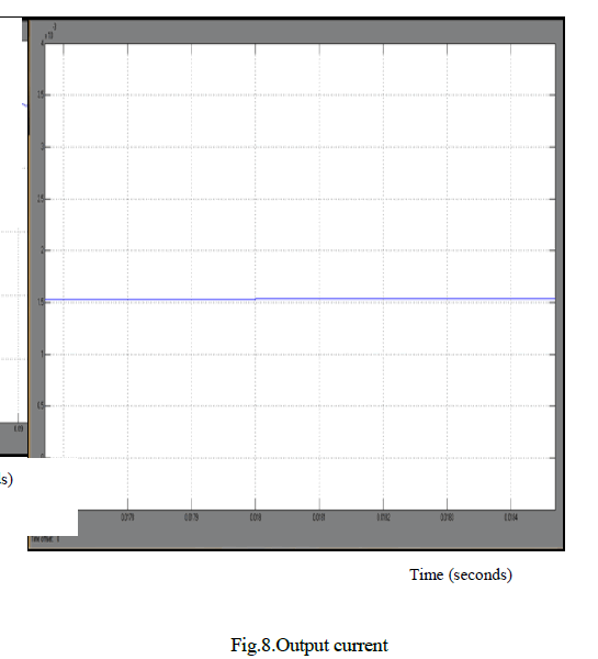
| An isolated feedback scheme with low-standby power for forward converter has been proposed. By this method under no-load condition opto-coupler consumes current nearly equal to zero i.e. 1.85*10-4 A. Thus the standby power consumption is reduced to .6mW. Simulation result show significant improvement in no-load efficiency of the forward converter. It can be used for other converter topologies also. It’s application may include ATX power supplies for computers, low voltage battery chargers, server power supplies. |
References |
|