Keywords
|
| FACTS, power quality, sag and swell mitigation, distributed power flow controller. |
INTRODUCTION
|
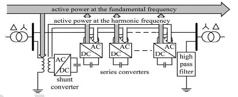
| Recent developments in the electric utility industry are encouraging the entry of power quality issue [1]. Extending from the generation units to the utility customers, power quality is a measure of how the elements affect the system as a whole [2]. From customer point of view, the power quality issue is concerned about current, voltage or frequency deviation which results in power failure [3]. To solve the power quality problem in such a situation, the power electronic devices such as flexible alternating-current transmission system (FACTS) and custom power devices (DVR) which are used in transmission and distribution control, respectively, should be developed [4], [5], [6]. The impact of transient parameters in majority of transmission lines problems such as sag (voltage dip), swell (over voltage) and interruption, are also considerable [1]. To mitigate the mentioned power quality problems, the utilization of FACTS devices such as power flow controller (UPFC) and synchronous static compensator (STAT-COM) can be helpful [7] , [8]. In [9], the distributed power flow controller (DPFC) is presented which has a similar configuration to UPFC structure. As shown in Fig. 1, the DPFC is composed of a single shunt converter and multiple independent series converters which is used to balance the line parameters, such as line impedance, transmission angle and bus voltage magnitude [9], [10]. To detect the voltage sags and determine the three single-phase reference voltages of DPFC, the SRF method is also proposed as a detection and determination method. The work in this paper is organized as follows: the DPFC operation principle is debated in Section II. In Section III, the control strategy of DPFC based on SRF method is proposed. The impact of DPFC in power quality enhancement is investigated in Section IV. Finally, the case study and its simulation results are analyzed in the last part of this work. |
DPFC STRUCTURE
|
| The basic issues in DPFC principle are DC-link elimination and using 3rd-harmonic current to active power exchange. In the following subsections, the DPFC basic concepts are explained. |
A. Eliminate DC-Link and Power Exchange
|
| Within the DPFC, the transmission line is used as a connection between shunt converter output and AC port of series converters, instead of using DC-link for power exchange between converters. The method of power exchange in DPFC is based on power theory of non-sinusoidal components [9]. Non-sinusoidal voltage and current can be presented as the sum of sinusoidal components at different frequencies. It is the main result of Fourier analysis. The |
| product of voltage and current components provides the active power. Since the integral of some terms with different frequencies are zero, so the active power equation is as follow: |
 |
| Where Vi and Ii are the voltage and current at the ith harmonic frequency, respectively, and φi is the angle between the voltage and current at the same frequency. Equation. 1 expresses the active powers at different frequencies are independent from each others. Thus, the converter can absorb the active power in one frequency and generates output power in another frequency. Assume the DPFC is located in transmission line of a two-bus system; therefore, the power supply generates the active power and the shunt converter absorbs it in fundamental frequency of current. Meanwhile, the third harmonic component is trapped in Y-Δ transformer. Output terminal of the shunt converter injects the third harmonic current into the neutral of Δ-Y transformer. Consequently, the harmonic current flows through the transmission line. This harmonic current controls the dc voltage of series capacitors. Fig. 2 illustrates how the active power is exchanged between the shunt and series converters in the DPFC. |
B. The DPFC Advantages
|
| The DPFC in comparison with UPFC has some advantages, as follows: |
| 1) High control capability. |
| The DPFC can control all parameters of transmission network: line impedance, transmission angle and bus voltage magnitude. |
| 2) High reliability. |
| The series converters redundancy increases the DPFC reliability during converters operation [10]. It means, if one of series converters fails, the others can continue to work. |
| 3) Low cost. |
| The single-phase converters rating, in comparison with three-phase converters is very low. Furthermore, the series converters, in this configuration, no need to any voltage isolation to connect in line. We can use the single turn transformers for series converters hanging. To explore the feasibility of the DPFC, a case study which is to use DPFC to replace UPFC of the Korea electric power corporation (KEPCO) is investigated. To achieve the same control capability as the UPFC, the DPFC construction requires less material [9]. |
III. DPFC CONTROL BASED ON SRF METHOD
|
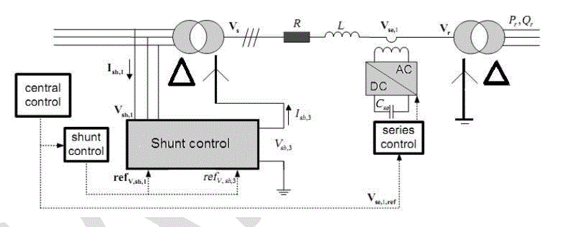
| The DPFC has three control strategies: central controller, series control and shunt control, as shown in Fig. 3. |
| A. Central Control |
| This controller manages all the series and shunt controllers and sends reference signals to both of them. |
| B. Series Control |
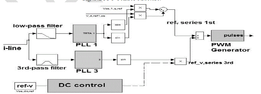
| Each single-phase converter has its own series control through the line. This controller inputs are series capacitor voltages, line current and series voltage reference in dq-frame. Any series controller has one low-pass and one 3rd-pass filter to create fundamental and third harmonic current respectively. Two single-phase phase lock loop (PLL) are used to take frequency and phase information from network [11]. The simulated diagram of series controller is shown in Fig. 4 |
| C. Shunt Control |
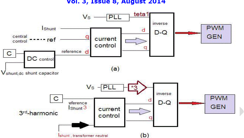
| The shunt converter includes a three-phase converter which is back-to-back connected to a single-phase converter |
| The three-phase converter absorbs active power from grid at fundamental frequency and controls the dc voltage of capacitor between this converter and single-phase one. The shunt control structure block diagram is shown in Fig. 5. |
| D. Proposed Detection and Determination Methods |
| To detect the voltage sags and determine the three single phase reference voltages of DPFC, the SRF method is introduced as a detection and determination method. The line-to-neutral voltages of grid in the pre-sag state are convicted from abc coordinate system to SRF (dq0) as the first step of this method. Then, the dq0 values of actual and reference line-neutral grid voltages are compared which the existence of the difference between them is representation of voltage sag and considered as the dq0 values of DPFC desired injected voltages. |
 |
 |
| The reference dq- component of DPFC desired injected voltages in the SRF, respectively. |
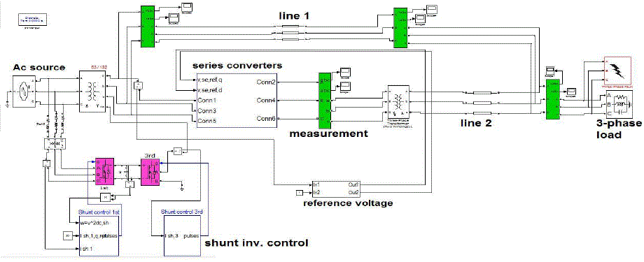
| This modeling has been developed using Mat lab/Simulink environment as shown in Fig. 6. The system is simulated with a three-phase source connected to a non-linear load. The simulation parameters are listed in Table 1. The supply is connected to load through the parallel transmission lines including the transmission line 1 and 2. The parallel transmission lines have same length. The DPFC is incorporated in transmission line 2. For analyzing dynamic performance, the inductive and capacitive loads are connected. The fault should be connected near the load to receive transient analysis. The shunt three-phase converter is connected to the transmission line 2 in parallel through a Y-Δ three-phase transformer, and series converters are distributed through this line. |
V. SIMULATION RESULTS
|
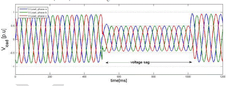
| The case study, considering sag/swell condition is implemented in single machine infinite bus system and analyzed results are as follows. To analyze voltage dip, a three-phase fault near the system load, as shown in Fig. 6 is created. The time duration for this fault is 0.5 seconds (500-1000 ms). The three-phase fault causes observable voltage sag during this time, as shown in Fig. 7. The voltage sag value is about 0.5 per unit. The DPFC can compensate the load voltage sag effectively. The voltage sag mitigation with DPFC is shown in Fig. 8. |
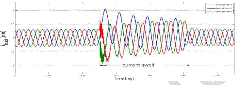
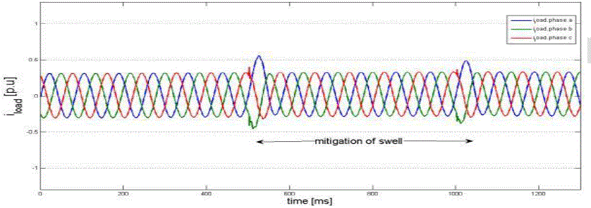
| After creating three-phase fault, Fig. 9 depicts the load current swell around 1.1 per unit. The fault time duration is 0.5 seconds. In this case, after implementation of the DPFC, the load current magnitude is comparatively come down. The current swell mitigation for this case can be observed from Fig. 10. |
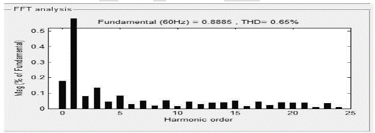
| The load voltage harmonic analysis, using fast Fourier transform (FFT) of power GUI window by Simulink, as shown in Fig. 11. It can be seen, after DPFC implementation in system, the odd harmonics are reduced within acceptable limits and total harmonic distortion (THD) of load voltage is minimized. |
VI. CONCLUSION
|
| The power quality enhancement of the power transmission systems is an vital issue in power industry. In his study, the application of DPFC as a new FACTS device, in the voltage sag and swell mitigation of a system composed of a threephase source connected to a non-linear load through the parallel transmission lines is simulated in Matlab/Simulink environment. The voltage dip is analyzed by implementing a three-phase fault close to the system load. To detect the voltage sags and determine the three single phase reference voltages of DPFC, the SRF method is used as a detection and determination method. The obtained simulation results show the effectiveness of DPFC in power quality enhancement, especially in sag and swell mitigation. |
Tables at a glance
|
 |
| Table 1 |
|
Figures at a glance
|
 |
 |
 |
 |
| Figure 1 |
Figure 2 |
Figure 3 |
Figure 4 |
 |
 |
 |
 |
| Figure 5 |
Figure 6 |
Figure 7 |
Figure 8 |
 |
 |
 |
|
| Figure 9 |
Figure 10 |
Figure 11 |
|
|
| |
References
|
- J. Faiz, G. H. Shahgholian, and M. Torabian, “Design and simulation of UPFC or enhancement of power quality in transmission lines,” IEEEInternational Conference on Power System Technology, vol. 24, no. 4, 2010.
- E. Emanuel and J. A. McNeill, “Electric power quality,” Annu. Rev. Energy Environ, 1997.
- N. R. Patne and K. L. Thakre “Factor affecting characteristics of voltage sag due to fault in the power system,” Serbian Journal of Electricalengineering. vol. 5, no.1, 2008.
- J. R. Enslin, “Unified approach to power quality mitigation,” in Proc. IEEE Int. Symp. Industrial Electronics (ISIE ’98), vol. 1, 1998.
- B. Singh, K. Al-Haddad, and A. Chandra, “A review of active filters for power quality improvement,” IEEE Trans. Ind. Electron. vol. 46, no. 5,pp. 960–971, 1999.
- M. A. Hannan and A. Mohamed, member IEEE, “PSCAD/EMTDC simulation of unified series- shunt compensator for power qualityimprovement,” IEEE Transactions on Power Delivery, vol. 20, no. 2, 2005.
- L. Olimpo and E. Acha, “Modeling and analysis of custom power systems by PSCAD/EMTDC,” IEEE Trans. Power Delivery, vol. 17, no.1,pp. 266–272, 2002.
- P. Pohjanheimo and E. Lakervi, “Steady state modeling of custom power components in power distribution networks,” in Proc. IEEE PowerEngineering Society Winter Meeting, vol. 4, Jan, pp. 2949–2954, 2000.
|