Keywords
|
| 1-phase Cycloconverter, Split phase Induction Motor, PWM pulse generator, IGBT MATLAB R (2010a). |
INTRODUCTION
|
| Analysis of induction motors controlled with Cycloconverter has been investigated extensively .The single phase induction motor in its simplest form is structurally the same as a poly phase induction motor having a squirrel cage rotor, the only difference is that the split phase induction motor has single winding on the stator. The split phase induction motor is the most commonly used motor in the utility network which produces mmf stationary in space but alternating in time, a polyphase stator winding carrying balanced currents produces mmf rotating in space around the air gap and constant in time with respect to an observer moving with the mmf Split phase induction motors are usually built with small power, they are widely used in domestic and commercial applications. This paper shown a speed control scheme for a split phase induction motor fed with Cycloconverter. Cycloconverter are used in very large variable frequency drives with ratings from few megawatts up to many tens of megawatts.. A single-phase input Cycloconverter is shown in Fig.1, single-phase input to single-phase output Cycloconverter is shown in Fig.4, the simplest Cycloconverter circuit..The single phase induction motor in its simplest form is structurally the same as a poly phase induction motor having a squirrel cage rotor, the only difference is that the split phase induction motor has single winding on the stator. The split phase induction motor is the most commonly used motor in the utility network. which produces mmf stationary in space but alternating in time, a polyphase stator winding carrying balanced currents produces mmf rotating in space around the air gap and constant in time with respect to an observer moving with the mmf. Split phase induction motors are usually built with small power, they are widely used in domestic and commercial applications. IGBT have the advantage for high speed, high power switching for building PWM controlled Cycloconverter. Section II gives you overview of the IGBT built Cycloconverter with its features and basic operation. Section III deals with modeling of Split phase induction motor where the speed and torque equation are mathematically derived. Section IV deals with PWM generator how a PWM pulse is generated and useful. Section V deals with the desired simulation result for pwm controlled Cycloconverter. Section VI deals with future application and scope and section VII is conclusion. |
CONCEPT OF CYCLOCONVERTER MODEL
|
| The Cycloconverter model is constructed. To begin, all of the input voltages are constructed using sinusoids as the input. Rather than producing the line voltages in addition to the phase output voltages, the phase voltages has shifted forward 30 degrees to produce the timing waveforms as in Fig. 5.1. The reference waveform is then added, and the timing waveforms are transformed into those in Fig. 5.2. At this point the construction of the output waveforms begins; Boolean variables contain the information of which IGBT in each of the converters has most recently switched on. That IGBT remains on until the firing waveforms crosses the zero boundaries at either a positive or negative edge, which fires the next IGBT, automatically turning another of the switches off according to the switching pattern. Again, this IGBT remains on until two more IGBTs have been triggered. As each IGBT directly corresponds to one of the phase voltage waveforms, these waveforms are simply translated directly to the output while their corresponding IGBT is on. This produces exactly the “cut and paste” type of waveform that is produced at the outputs of each of the positive and negative converters in the case of a real Cycloconverter. Lastly, these waveforms are averaged, an effect that happens because of the inter-group reactor separating them. The inductance acts to sum the integrals of the voltage together, acting in effect as an averaging device. |
IGBT Fundamentals:-
|
| The Insulated Gate Bipolar Transistor (IGBT) is a minority-carrier device with high input impedance and large bipolar currentcarrying capability. Many designers view IGBT as a device with MOS input characteristics and bipolar output characteristic that is a voltage-controlled bipolar device. To make use of the advantages of both Power MOSFET and BJT, the IGBT has been introduced. It’s a functional integration of Power MOSFET and BJT devices in monolithic form. It combines the best attributes of both to achieve optimal device characteristics. |
| The IGBT is suitable for many applications in power electronics, especially in Pulse Width Modulated (PWM) servo and threephase drives requiring high dynamic range control and low noise. It also can be used in Uninterruptible Power Supplies (UPS), Switched-Mode Power Supplies (SMPS), and other power circuits requiring high switch repetition rates. IGBT improves dynamic performance and efficiency and reduced the level of audible noise. It is equally suitable in resonant-mode converter circuits. Optimized IGBT is available for both low conduction loss and low switching loss. |
The main advantages of IGBT over a Power MOSFET and a BJT are:
|
| 1. It has a very low on-state voltage drop due to conductivity modulation and has superior on-state current density. So smaller chip size is possible and the cost can be reduced. |
| 2. Low driving power and a simple drive circuit due to the input MOS gate structure. It can be easily controlled as compared to current controlled devices (Thyristor, BJT) in high voltage and high current applications. |
| 3. Wide SOA. It has superior current conduction capability compared with the bipolar transistor. It also has excellent forward and reverse blocking capabilities. The IGBT is suitable for scaling up the blocking voltage capability. |
The main drawbacks are:
|
| 1. Switching speed is inferior to that of a Power MOSFET and superior to that of a BJT. The collector current tailing due to the minority carrier causes the turnoff speed to be slow. |
| 2. There is a possibility of latch up due to the internal PNPN thyristor structure. |
![image]() |
![image]() |
| In this dissertation work Cycloconverter & split phase induction motor has been studied. The Cycloconverter is to increase the efficiency & performance of the system. The objective of dissertation is to analysis and design of a Cycloconverter fed different types of motor. Cycloconverter examine currently used controlling of speed which focuses on monitoring the specific changes in rotor Speed. In the present work the study has been carried out on the main & aux. currents, electromagnetic torque, for split phase induction motor controlling of speed. Which is primarily based on the generation of virtual data through a simulation program, which allows the change in split phase induction motor performance due to the changes of parameters as a effect of the different loads. The diagnosis of a different speed always commences with the basic physical understanding of the work. In order to this phase, the knowledge of the well-tested models allowing the simulation of the different controlling condition, which is fundamental prime requirement for obtaining the pattern classification. One of the aims of this work is to study the indicators of Cycloconverter by speed control of split phase induction motor. |
MODELING OF SPLIT PHASE INDUCTION MOTOR
|
| Split phase induction motors are usually constructed with two windings on the stator side and squirrel cage winding in the rotor side. The auxiliary winding is used to produce a rotating field to start the motor. The axis of the auxiliary winding is placed 90 electrical ahead of the main winding as shown in Fig.4. The lively simulation of the motor is presented in the stationary d-q frame to facilitate the application of the inverter and, later on, the feedback regulators. Since the axis of the main and auxiliary windings are already orthogonal, the stationary d-q axes are chosen aligned with the orthogonal axes of the physical windings. The squirrel cage rotor is represented by equivalent two coils transformed to the stationary d-q axis as shown in FIGURE |
![image]() |
![image]() |
| Since the two stator windings; namely the main and auxiliary coils, have different number of turns, they will yield different mutual reactance. Therefore, a transformation is made to transfer the auxiliary winding to an equivalent winding with the same number of turns as that of the main coil. The new variables referred to the equivalent coil are given as follows: |
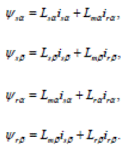 |
| The voltage equation of the motor can be written in the d-q stationary frame as follows: |
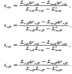 |
| The equations of motion are given by: |
 |
 |
PWM GENERATOR
|
| Generate pulses for carrier-based two-level pulse width modulator (PWM) in Converter Bridge. The pulses are generated by comparing a triangular carrier waveform to a reference modulating signal. The modulating signals can be generated by the PWM generator itself, or they can be a vector of external signals connected at the input of the block. One reference signal is needed to generate the pulses for a single- or a two-arm bridge, and three reference signals are needed to generate the pulses for a three-phase, single or double bridge. The PWM drive draws almost unity power factor current from the supply and is maintained at constant level at all motor speeds. SPWM (Sinusoidal Pulse Width Modulation) technique is used The fundamental magnitude of the output voltage from a Cycloconverter can be controlled to be constant by exercising control within the Cycloconverter itself that is no external control circuitry is required. The most efficient method of doing this is by Pulse Width Modulation (PWM) control used within the Cycloconverter. In this scheme the Cycloconverter is fed by a fixed input voltage and a controlled ac voltage is obtained by adjusting the on and the off periods of the Cycloconverter components. The advantages of the PWM control scheme are [10]: a) The output voltage control can be obtained without addition of any external components. |
| b) PWM minimizes the lower order harmonics, while the higher order harmonics can be eliminated using a filter. The disadvantage possessed by this scheme is that the switching devices used in the Cycloconverter are expensive as they must possess low turn on and turn off times, nevertheless PWM operated are very popular in all industrial equipments. PWM techniques are characterized by constant amplitude pulses with different duty cycles for each period. The width of these pulses are modulated to obtain Cycloconverter output voltage control and to reduce its harmonic content. There are different PWM techniques which essentially differ in the harmonic content of their respective output voltages, thus the choice of a particular PWM technique depends on the permissible harmonic content in the Cycloconverter output voltage. |
SIMULATION RESULT
|
| Simulink model is shown in Fig. 1&2. The objective of this paper is to analyze the speed of induction motor performance. The stator of a split phase induction motor has two windings, the main winding and auxiliary winding. Since, the d-q axis model of an induction motor is only valid for sinusoidal input voltage, the Cycloconverter voltage output must be decomposed into its fundamental. Fig. (3-14) shows output phase voltages and currents for input frequency is 2,3 4 times the output frequency of the 1- phase Cycloconverter. |
| shows output phase voltages and currents for input frequency is 3 times the output frequency of the 1-phase Cycloconverter. From control standpoint, the proposed Cycloconverter simulation result shown in Figure. In order to get a better understanding of the control system and to verify the control techniques described by researcher in previous research paper [2], a Simulink model was developed as shown in Figure 6. The simulation starts with the 50 Hz reference sine wave is generated. |
| From the above discussion and form the waveform shown in fig following point may be noted. The average output voltage waveform is far from sinusoidal since the firing angle is held constant .The current waveform not repeated after every cycle Fig.8. Some circulating current is allowed to flow from the positive converter to the negative converter. In this case a circulating current limit in reactor is connected between the positive and negative converter. In order to obtain reasonably good sinusoidal or square output voltage waveform using line commutated two quadrant converter and eliminating the possibility of short circuit of the supply voltage, the output frequency is limited to a value much lower than supply frequency. |
FUTURE APPLICATIONS OF CYCLOCONVERTER
|
| Many of the problems with employing Cycloconverter in real power applications result directly because of the problems with sub harmonics. If generators for the Cycloconverter or the Cycloconverter loads are not robust enough to deal with imperfect power quality, the Cycloconverter is forced into very strict operating conditions. Output frequency must be limited in order to contain harmonics within a filterable spectrum. However, these limitations are all based on the assumption that the input power for the Cycloconverter is coming from a standard generator. Current technology has been able to expand the possible usage of Cycloconverter away from these limiting assumptions. The recent increase in distributed power generation has led a flurry of research on micro turbines. Micro turbines are an integration of gas combustion engines and electric generators, which produces an output power on the order of hundreds of kilowatts at tens of kilohertz. This is an extreme jump from diesel generators, which often produce power at 60 Hz. However solid state switching limitations are quickly lifting with the incorporation of new device technologies and micro turbine research continues to produce varied mode ls. It is very possible that there will soon be a possible combination of higher frequency generators and Cycloconverter. The other technology that has restricted the development of the Cycloconverter to slow operating machinery is the limited switching speeds of most present day power electronic switches. However, with better switching technology such as higher speed thyristors or new high power integrated gate bipolar transistors Cycloconverter could be used with these high frequency generators. This would effectively eliminate output-to-input ratio issues including the unfilterable sub harmonics and inter harmonics contained in both outputs and inputs. |
CONCLUSION
|
| The PWM controlled Cycloconverter circuits is designed and simulated and desired results are obtained. Single phase Cycloconverter used for Single phase motor to generate supply torque characteristics that matches with demand torque characteristics of particular machine by the use of designing Cycloconverter different desired frequency are obtained to equalize the torque demand of machine. This different frequency of Cycloconverter is also useful to replace flywheel from the operating machine which reduces the cause of torsional vibration and fatigue damage of machine. The paper proposed a feedback control scheme of Cycloconverter fed split phase induction motor. Furthermore, it provides means for limiting the slip and consequently the motor current. This means a reduction in the Cycloconverter rating and better efficiency. This contribution will report on the results obtained using matlab for single phase Cycloconverter coupled to an induction motor. |
ACKNOWLEDGEMENT
|
| We are grateful to our Departments, for giving us the opportunity to execute this Research Paper, which is an integral part of the curriculum in M.Tech program at the Punjab Technical University. we would also like to take this opportunity to express heartfelt gratitude for our project guides ,who provided us with valuable inputs at the critical stages of this paper execution. we would like to acknowledge the support of every individual who assisted me in making this paper a success and I would like to thank our H.O.D Tejinnder singh Saggu of Electrical Dept in AIET Faridkot and Mr. Arun Kumar Yadav from SITM lucknow. for their guidance, support and direction without which project would not have taken shape. we am also very thankful to my parents for providing continuous guidance and wholehearted support throughout the Research Paper.we am also thankful to the staff of Department for cooperating with me during the course of my Research Paper. |
Figures at a glance
|
 |
 |
 |
 |
 |
| Figure 1 |
Figure 2 |
Figure 3 |
Figure 4 |
Figure 5 |
 |
 |
 |
 |
 |
| Figure 6 |
Figure 7 |
Figure 8 |
Figure 9 |
Figure 10 |
 |
 |
 |
 |
| Figure 11 |
Figure 12 |
Figure 13 |
Figure 14 |
|
References
|
- Maamoun, A., "Development of cycloconverters," Canadian Conference on Electrcal and Computer Engineering, 2003. IEEE CCECE Vol.1,4-7, pp.521 –524May 2003.
- SandeepPande , HarshitDalvi, “Simulation of Cycloconverter Based Three Phase Induction Motor” International Journal of Advances in Engineering &Technology (IJAET), ISSN: 2231-1963 Vol. 1, Issue 3, pp.23-33 July 2011.
- ShlomiEitan and Raul Rabinovici, “On Line Simulation Models of Electric Drives” Proceedings of International Conference on Electrical Machines, 2008,978-1-4244-1736-0/08, pp. 1-6 IEEE 2008.
- Zahirrudin Idris, Mustafar Kamal Hamzah, and NgahRamziHamzah “Modeling & Simulation of a new Single-phase to Single-phase Cycloconverter based onSingle-phase Matrix Converter Topology with Sinusoidal Pulse Width Modulation Using MATLAB/Simulink” pp.1557-1562 IEEE PEDS 2005.
- TaufikTaufik , Jesse Adamsonand Anton SatriaPrabuwono “Pulse Density Modulated Soft-Switching Single-Phase Cycloconverter” IEEE Applied PowerElectronics Colloquium (IAPEC), pp.189-194, 2011.
- Rezgar Mohammed Khalil and Maamoon Al-Kababjie, “Modeling and Simulation of multi-pulse Cycloconvereter-fed AC induction motor and study of outputpower factor” Al-Rafidain Engineering Vol.15 No.1, pp. 1-14 2007.
- A. M. Abdel-Halim, H. G. Hamed, and K. M. Hassaneen, “Modeling and Simulation of VSI-FED Induction Motors”, Middle East Power SystemsConference (MEPCON’2000) pp.80-84, 2000.
- D.M. Manjure and E. Makram ”Effect of converter Drive on Power Systems”, Middle East Power Systems Conference (MEPCON’2000), March 28-30, pp.28-32, 2000.
- Paul C. Krause, Oleg Wasynczuk, and Scott D. Sudhoff, “Analysis of Electric Machinery and Drive Systems”, 2nd ed., ISBN: 978-0-471-14326-0, Wiley-IEEEPress, 2002.
- Chen-MunOng, “Simulation of Electric Machinery”, ISBN: 0-13-723785-5, Prentice Hall, NJ 07458, 1998.
- Songchun Zhang, Fenglin Wu, ShminShen, Shuchun Yang, “A Digital Controller Based Cycloconverter Fed Drive”, pp. 637-641,EEE Transaction, 1997.
- Z.Wang and Y. Liu, “Modeling and Simulation of a Cycloconverter Drive System for Harmonic studies”, IEEE Transactions on Modern Electronics,vol. 47, no. 3, , pp. 533-541, June 2000.
- M. Adli, R. Mecke, F.Palis, “ A New Control Strategic of Quasi- Cycloconverter Fed Induction Motor drive” in 1993, The European Power ElectronicsAssociation, pp. 82-87, 1993.
- H. Li, B.Ozpineci and B.K.Bose, “A Soft-Switched High Frequency Non-Resonant Link Integral Pulse Modulated DC-DC Converter for AC Motor Drive”,Conference Proceedings of IEEE-IECON, Aachen/Germany, vol. 2, pp 726-732, 1998.
- J. Pontt, F. Rojas, J. Rodríguez, J. Rebolledo, J. S. Martin, I. Illanes,E. Cáceres, R. Aguilera, and W. Valderrama, “Issues on reliability of cycloconverter-fedhigh- power gearless mill drives” in Proc. Int. Conf. Conminution’06, Perth, Australia, Mar. 15–17, 2006.
- Jorge O. Pontt, José P. Rodríguez, Jaime C. Rebolledo, Kurt Tischler, and Norbert Becker “Operation of High-Power Cycloconverter-Fed Gearless Drivesunder Abnormal Conditions” IEEE Transactions on Industry Applications, vol. 43, no. 3, pp. 814-819, May/June 2007.
- PrasidSyam, GautamBandyopadhyay, Prasanta K. Nandi, and Ajit K. Chattopadhyay “Simulation and Experimental Study of Interharmonic Performance of aCycloconverter-Fed Synchronous Motor Drive” IEEE Transactions on Energy Conversion, vol. 19, no. 2, pp. 325-332, June 2004.
- Joseph Edward Shigley, John Joseph VickerJr.,”Theory of Machines & Mechanisms”, Ed. 2nd, McGraw Hill International, 1995.
|