Keywords
|
| Brushless DC (BLDC) motor, Sensorless Control, Zero Crossing Point (ZCP), Back EMF (BEMF) difference. |
INTRODUCTION
|
| BLDC motors have emerged as the recent choice of researchers and scientists. In this type of DC motor, commutation is done electronically instead of using brushes. A BLDC motor drive system requires an inverter and a rotor position sensor to perform the commutation process. The motor which is powered by a rectangular current requires only six discrete rotor position. It can be detected by using Hall sensors. There are several drawbacks when such types of position sensors are used. These sensors increase the cost of the motor and reduce simplicity and reliability of the system due to the extra components and wiring. Especially, hall sensors increase the size of the motor and they are temperature sensitive since they are mounted inside. For these reasons, they limit the operation of the motor in practice [1]. |
| To overcome these disadvantages of using Hall sensors, lots of research is being done in sensorless drives. Various methods are implemented for sensorless driving of BLDC motor. These methods includes detection of back EMF (BEMF) of the motor, detection of the conducting state of freewheeling diode in the unexcited phase [1], back EMF integration method, detection of stator third harmonic voltage components. Of the above mentioned methods, BEMF detection method is commonly used these days. In this method the zero crossing point (ZCP) of BEMF is determined and thereby the commutation point is determined. The BEMF of a motor can be detected when the motor starts running at high speed. |
| BEMF of a motor cannot be detected directly. One well known method is terminal voltage detection method. The difference between the terminal voltage of the open phase and a virtual neutral point voltage which is created by connecting the three phases to a common point through a resistor is sensed. By monitoring the voltage difference, the zero crossing point (ZCP) can be detected and it is used to commutate a motor. Another method is that the ZCP is detected by matching the terminal voltage with the half of the DC link voltage. Both methods require low pass filters to eliminate the chopped pulses generated by PWM from the terminal voltage. Virtual neutral induces electrical noise into the system which affects the system performance. |
| This paper proposes a new sensorless drive scheme for a BLDC motor. Instead of detecting the ZCP of the open phase BEMF, the ZCP of the BEMF difference corresponds to the commutation point of a BLDC motor exactly and thus the optimal performance is guaranteed. |
MODELING OF BLDC MOTOR
|
| BLDC drive with sensor, consist of a BLDC motor, control circuit and Hall sensor for position information. By knowing the position information, inverter switches are commutated by generating PWM signals with the suitable duty ratio. Three Hall sensors are used for position detection of the BLDC motor. A general BLDC motor has three phase stator windings and is driven by an inverter which constitutes of six switches. Fig. 1 shows the equivalent circuit of a star connected BLDC motor and the inverter topology [2][3]. |
| The modeling is based on the following assumptions: |
| (1) The motor is not saturated. |
| (2) Stator resistances of all windings are equal and self and mutual inductances are constant. |
| (3) Power semiconductor devices in the inverter are ideal. |
| (4) Iron Losses are negligible. |
| The voltage equation of a BLDC motor can be expressed as: |
 |
| Where |
| Va, Vb and Vc are the stator phase voltages; R is the stator resistance per phase; Ia, Ib and Ic are the stator phase currents; L is the self-inductance per phase and ea, eb and ec are the back electromotive forces. BEMF equation of each phase should be as follows: |
 |
| where |
| Kw is back EMF constant of one phase [V/rad.s-1], |
| θe - electrical rotor angle [° el.], |
| ω - rotor speed [rad.s-1]. |
| The back EMF is a function of rotor position which is represented as fa(θe), fb(θe), fc(θe) with limit values between -1 and +1. |
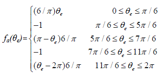 |
| Accordingly fb (θe) and fc (θe) can be designed |
| Total torque output can be represented as summation of each phase |
| Total torque output is given by: |
 |
| where |
| Te is total torque output [Nm], |
| Also, |
 |
| where |
| TL - Load torque [Nm], |
| J - Inertia of rotor and coupled shaft [kgm2], |
| B - Friction constant [Nms.rad-1]. |
| The electrical rotor angle is equal to the mechanical rotor angle multiplied by the number of pole pairs p: |
 |
| where |
| θm is mechanical rotor angle [rad]. |
CONVENTIONAL METHOD OF SENSORLESS CONTROL
|
| In this method ZCP of the BEMF is detected directly. The BEMF and current waveforms are as shown in the Fig. 2. |
| For typical operation of a BLDC motor, the phase current and back-EMF should be aligned to generate constant torque. The commutation point shown in Fig. 2 can be estimated by the ZCP of back-EMFs and a 30° phase shift, using a six-step commutation scheme through a three-phase inverter for driving the BLDC motor. The conducting interval for each phase is 120 electrical degrees [4]. Therefore, only two phases conduct current at any time, leaving the third phase floating. In order to produce maximum torque, the inverter should be commutated every 60° by detecting zero crossing of back EMF on the floating coil of the motor, so that current is in phase with the back EMF. |
| By using the waveforms in Fig. 2, the following truth table is developed. |
| Based on the truth table, a block diagram is designed to generate appropriate commutation signal which is simulated and verified using MATLAB/Simulink. |
| The terminal voltage of the floating phase is directly proportional to the BEMF and the ZCP can be detected by comparing terminal voltage of floating phase with the half of DC link voltage or the virtual neutral voltage. When using terminal voltage measurement method, the phase difference between the ZCP and the commutation instant should be compensated in some manner for proper operation of a motor. The terminal voltage induced by PWM is the combination of a DC component and harmonic components. Since harmonic components are acting as noise, especially on the virtual neutral voltage, the first order low pass filter is adopted in order to eliminate the noise. Another filter is designed to make the commutation point lag 30° after the zero crossing point is detected. It makes the phase compensation difficult and thus the torque ripple increases due to inaccurate commutation. |
PROPOSED METHOD OF SENSORLESS CONTROL
|
| Instead of using phase BEMF, the proposed method utilizes difference in BEMF of two phases. BEMF difference waveform is shown in Fig. 3. |
| From the above figure it is clear that in the proposed method the commutation can be done at the ZCP itself. Thus the optimal performance is guaranteed by using this signal for commutation. The ZCP of the terminal voltage difference is identical to the ZCP of the BEMF difference and thus it can be used as commutation signal directly without phase compensation. |
| By using the waveforms in Fig. 3, the following truth table is developed. |
| Using the proposed scheme, the conventional starting procedure is not required theoretically since the BEMF can be sensed as soon as the motor rotate [3]. (The motor can be switched to sensorless drive within 60° rotation in practice.) |
SIMULATION RESULTS
|
| Simulations of conventional and proposed sensorless drive scheme are carried out in MATLAB/Simulink. The BLDC motor specifications used for simulation is shown in Table III. |
| A. Simulation Block Diagram of Phase EMF Detection Method |
| The block is designed based on the values given in Table I. |
| B. Simulation Block Diagram of BEMF Difference Method |
| C. Waveforms |
| Waveforms of phase BEMF (red) and BEMF difference (blue) are shown. The BEMF difference waveform lags behind phase BEMF waveform. From this it is evident that the commutation can be done at the same instant of zero crossing detection. |
| Rotor speed in both conventional method and proposed method are same. Thus we can say than the performance of the motor is not affected by the proposed method. |
CONCLUSION
|
| A new sensorless drive scheme by detecting ZCP of BEMF difference is analysed in this paper. Optimal performance of the motor drive system is guaranteed by using this scheme. From the simulation results it is concluded that the desired output of the machine can obtain by this method as in the case of conventional sensorless technique. The neutral voltage is not required in the proposed method; only the three motor terminal voltages need to be detected. The output of the system is analogous to the Hall sensor signal and thus it can be used for sensorless drive without phase compensation and starting procedure as that of BLDC drive with position sensor. A related further work is to design a sensorless speed controller based on the proposed scheme. |
Tables at a glance
|
|
|
Figures at a glance
|
 |
 |
 |
 |
| Figure 1 |
Figure 2 |
Figure 3 |
Figure 4 |
 |
 |
 |
 |
| Figure 5 |
Figure 6 |
Figure 7 |
Figure 8 |
|
References
|
- J. Gamazo-Real, E. V zquez-Snchez, and J. Gmez-Gil, "Position and speed control of brushless dc motors using sensorless techniques andapplication trends," Sensors, vol. 10, no. 7, pp. 6901-6947, 2010.
- S. Ogasawara and H. Akagi, “An approach to position sensorless drive for brushless dc motors,” IEEE Trans. Ind. Appl., vol. 27, no. 5, pp. 928–923, Sep./Oct. 1991.
- P. Pillay and R.Krishnan, “Modelling, Simulation, and analysis of permanent-magnet motor drives”, IEEE Trans. Ind. Appl, vol. 25, no. 2, pp.265-279, Mar/Apr 1989.
- Q. Jiang, C. Bi, and R. Huang, “A new phase-delay method to detect back EMF zero-crossing points for sensorless control of spindle motors,”IEEE Trans. Magnetics, vol. 41, no. 7, pp. 2287–2594, Jul. 2005.
- Dae-kyong Kim, Kwang-Woon Lee, Byung-Il Kwon, “Commutation Torque Ripple Reduction in a Position Sensorless Brushless DCMotor Drive,” IEEE Trans. on Power Electronics, vol. 21, no. 6, pp. 1762-1768, Nov. 2006.
- J. P. Jahnson, M. Ehsani, and Y. Guzelaunler, “Review of sensorless methods for brushless DC,” in Proc. IEEE IAS Annu. Meeting Conf.,Phoenix, AZ, 1999, pp. 143–150.
|