Keywords
|
| Brushless DC(BLDC) motor, current sensor, DC link, closed loop control. |
INTRODUCTION
|
| The permanent magnet brushless DC motors found wide applications in industry due to their high power density and ease of control. The brushless DC motors have high efficiency, low maintenance and low rotor inertia for their increased demand in servo, robotic and domestic applications. The BLDC motor is an AC synchronous motor with permanent magnets on the rotor and windings on the stator. Permanent magnets create the rotor flux and the energized stator windings create electromagnet poles. The rotor is attracted by the energized stator phase. By using the appropriate sequence to supply the stator phases, a rotating field on the stator is created and maintained. This action of the rotor chasing after the electromagnet poles on the stator is the fundamental action used in brushless permanent magnet motors. |
| For the operation of BLDC motor, the rotor position information is necessary. According to the rotor position, the phase windings are switched in a sequence to obtain the rotation. In most BLDC drives a current control loop is used to maintain the load current at some desired level. This is done by switching the constant DC link voltage across the motor windings. The current control loop requires the feedback currents from each phase. Conventionally it is provided by direct measurement of the winding currents by using separate current sensors. But the current sensors and the associated accessories increase the complexity, cost and size of the motor drives and reduce the reliability of the system. Therefore, reduction of the number of sensors is desirable in motor drives. Also the use of different current sensors can cause undesirable imbalance in phase currents as well as torque fluctuations due to differences in current sensor sensitivities. These drawbacks can be avoided by using a single current sensor placed on the DC link. Here an algorithm is presented to obtain the phase current values from the DC link current. |
MODELING OF BLDC MOTOR
|
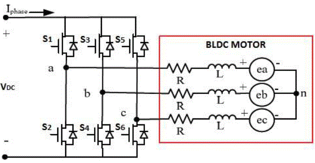
| The BLDC motor is modelled using three phase ABC variables. The equivalent circuit of a three phase BLDC motor is shown in fig. 1. |
| The phase voltage equations of BLDC motor can be written as, |
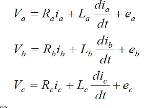 (1) (1) |
| where, |
| V ,V &V , are the respective phase voltages a b c i , i &i , are the phase currents a b c e , e &e , are the phase back emfs |
| 'R' is the stator resistance per phase, assumed to be equal for all phases, i.e. Ra= Rb= Rc= R |
| 'L' is the stator inductance per phase, assumed to be constant for all phases, i.e. La= Lb= Lc= L |
| Here the mutual inductance between the stator windings are neglected. |
| Taking the Laplace transform of the above equations, |
 (2) (2) |
| Rearranging above equations, we get the phase currents as |
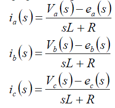 (3) (3) |
| The phase back emfs can be expressed as, |
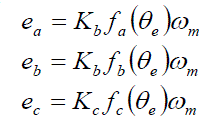 (4) (4) |
| where, |
| b K is the back emf constant |
| eθ is the electrical rotor position in rad |
| ωm is the rotor speed in mechanical rad/Sec |
 |
| The electromagnetic torque is given by |
 (6) (6) |
| The electromagnetic torque generated by the motor is also proportional to the torque constant( t K ) and product of current with electrical rotor position. |
 (7) (7) |
| The equation of motor for simple system is |
 |
| where, l T is the load torque, J is moment of inertia and B is the damping constant. Taking the Laplace transform of the equation (8) |
 (9) (9) |
| Rearranging the above equation |
 (10) (10) |
| The relationship between electrical rotor speed and position is given by |
 (11) (11) |
| where, |
| p is the number of poles |
| ωm is the rotor speed in mechanical rad/Sec |
| e θ is the electrical rotor position in rad |
THE SINGLE DC LINK CURRENT SENSOR TECHNIQUE
|
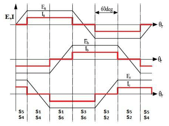
| The BLDC motor is supplied from a DC source through an inverter. The back emf and phase current waveforms for one complete cycle is shown in fig. 2. |
| For closed-loop current control of brushless DC motors, instantaneous phase currents are measured using current sensors. Such sensors are often bulky, heavy, and expensive. In single DC link current sensor technique a single current sensor is placed in the DC link. From the measured DC link current, the phase currents can be estimated. |
| In a BLDC motor two stator phases are energized at a time. So two switches of the inverter are conducting (one upper and one lower) at any instant. Since two phases of the motor are energized at any instant and the motor is star connected, the same current flows through them. Also this current is same as the DC link current, measured by the single DC link current sensor. From the DC link current, the phase currents are estimated according to the phase current waveforms in fig. 2. |
 |
 (13) (13) |
 (14) (14) |
| where, |
| a b c i , i , i are the instantaneous phase currents |
| dc i is the measured DC link current |
| e θ is the rotor position in electrical rad |
BLDC MOTOR DRIVE SCHEME
|
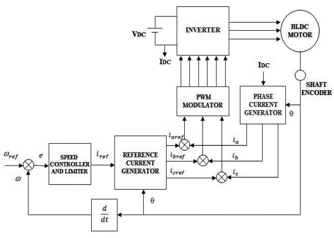
| The basic block diagram of the proposed BLDC drive is shown in fig. 3. |
| In the sensored BLDC drive, hall sensors or a shaft encoder is used to obtain the rotor position information. The drive control system consist of an outer speed loop for speed control and an inner current loop for current control. Conventionally three separate current sensors are used to measure the phase currents. But here only one current sensor is used, which is placed on the DC link. |
| A. Speed control |
| The speed control block uses a Proportional Integral(PI) controller. A PI controller attempts to correct the error between a measured process variable and desired set point by calculating and then outputting a corrective action that can adjust the process accordingly. The PI controller calculation involves two separate modes the proportional mode and the integral mode. The proportional mode determine the reaction to the current error, integral mode determines the reaction based recent error. The weighted sum of the two mode output as corrective action for the control element. The PI controller is widely used in the industry due to its ease in design and simple structure. The PI controller algorithm can be implemented as |
 (15) (15) |
| Here the input to speed controller is the speed error. The output of the controller is considered as a reference torque. A limit is put on the speed controller output depending on permissible maximum winding currents. |
| B. Current control |
| For current control the actual phase currents are compared with reference phase currents and the error is given to pwm current controller to produce the switching signals for the inverter switches. Depending on the rotor position, the reference current generator block generates three-phase reference currents by taking the value of reference current magnitude as ref i . The rotor position and reference currents are shown in Table 1. |
| The current control can be achieved by using a PI controller or a hysteresis controller. |
| PI control : In a BLDC motor, the electromagnetic torque produced is directly proportional to the magnitude of the stator current. The actual phase currents are compared with the reference currents and the error is fed to a PI controller, to reduce it to an acceptable value. Now it is compared with a triangular carrier to produce the pwm signals. |
| Hysteresis control : A hysteresis controller is designed to control the stator current, hence the output electromagnetic torque of the motor. It provides a fast response compared to the PI controller. The controller maintains the stator current within the predefined hysteresis band about the reference current value. Here the current error is given to hysteresis controller to obtain the pwm signals. |
SIMULATION AND RESULTS
|
| To evaluate the performance of the proposed system, simulation models have been established using MATLAB/SIMULINK. The performance of the drive with conventional method and the proposed single current technique were studied. The parameters of the BLDC motor used for simulation are, dc V = 24V, s R = 0.36Ω , s L = 0.6mH , P = 8, J = 48g-cm 2 , t K = 0.036Nm/A. |
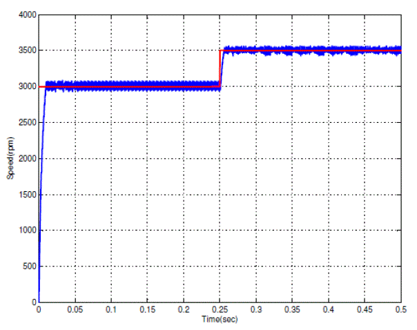
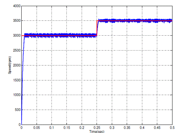
| The simulation results obtained from closed loop speed control is shown in fig. 4. |
| From the simulation results it is clear that in proposed method, the speed response of the drive remains same as that of the conventional method. So by using the proposed method, the number of current sensors required for closed loop control decreases. Also if the DC link sensor is placed on the ground line, insulated systems are not necessary and a low cost resistor can be used. |
CONCLUSION
|
| A new and simple method is proposed to reduce the cost and to improve the performance of the drive. The proposed method obtains the actual phase current values by using a single DC link current sensor, thus reducing the cost and the size of the drive. Also, if the current sensor is placed on the ground line, insulated systems are not necessary and a low cost resistor can be used. Here the undesirable imbalances in the phase currents as well as pulsating torque due to mismatched in the current sensor sensitivities is also avoided. The simulation results show that, by using the proposed method, drive gives the same closed loop performance as that of the conventional method. |
Tables at a glance
|
 |
| Table 1 |
|
Figures at a glance
|
 |
 |
 |
 |
 |
| Figure 1 |
Figure 2 |
Figure 3 |
Figure 4 |
Figure 5 |
|
References
|
- M. R. Feyzi, M. Ebadpour, S. A. KH. MozaffariNiapour, ArshyaFeizi, R. MousaviAghdam “A New Single Current Strategy for High-Performance Brushless DC Motor Drives”, International Conference on Electrical and Computer Engineering, IEEE CCECE 2011, pp. 419 -424.
- H. K. SamithaRansara, U. K. Madawala “A Low Cost Drive for Three Phase Operation of Brushless DC Motors”, International conference onIEEE Industrial Electronics Society, IECON 2011, pp. 1692 - 1697.
- R. Krishnan, Permanent Magnet Synchronous and Brushless DC Motor Drives, CRC Press, 2010.
- B. Akin, M. Bhardwaj, Trapezoidal Control of BLDC Motor Using Hall Sensors, Texas Instruments, 2010.
- C. Xia, Z. Li, T. Shi “A Control Strategy for Four Switch Three Phase Brushless DC Motor Using Single Current Sensor”, IEEE Trans. onIndustrial Electronics, vol. 56, no. 6, pp. 2058-2066, June 2009.
|