Keywords
|
| Three input boost converter, Hybrid power system, PV, Wind, Battery sources, state of charge (soc), and Terminal resistance. |
INTRODUCTION
|
| Photovoltaic (PV) energy appears quite attractive for electricity generation because of its noiseless, pollution-free, scale flexibility, and little maintenance. Because of the PV power generation dependence on sun irradiation level, ambient temperature, and unpredictable shadows, a PV-based Power system should be supplemented by other alternative energy sources to ensure a reliable power supply.) Wind power emerging as a promising supplementary power sources due to their merits of cleanness, high efficiency, and high reliability. Because of long startup period and slow dynamic response weak points of FCs [1], mismatch power between the load and the FC must be managed by an energy storage system. Batteries are usually taken as storage mechanisms for smoothing output power, improving startup transitions and dynamic characteristics, and enhancing the peak power capacity [2], [3]. Combining such energy sources introduces a PV/wind/battery hybrid power system. These converters Have received more attention in the literature because of providing simple circuit topology, centralized control, bidirectional power flow for the storage element, high reliability and low manufacturing cost and size. Two input converters based on flux additively in a multiwinding transformer are reported in [15]. Because there was no possibility of bidirectional operating of the converter, and complexity of driving circuits and output power limitation in [16], they are not suitable for hybrid systems. Three input converter are proposed based on structure of the dc–dc boost converter. The dc–dc boost converter is useful for combining several energy sources whose power capacity or voltage levels are different. |
MODELING OF PV PANEL
|
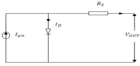
Fig. 1shows the equivalent circuit of the ideal photovoltaic cell. The basic equation from the theory of semiconductors [1] that mathematically describes the I-V characteristic of the ideal photovoltaic cell is,  |
| Where the symbols are defined as follows: |
| Ipv, cell is the current generated by the incident light (it is directly proportional to the Sun irradiation), |
| I0,cell is the reverse saturation or leakage current of the diode, |
| q is the electron charge (1.60217646 × 10⁻¹⁹ C), |
| k is the Boltzmann constant (1.3806503 × 10⁻²³ J/K), T (in Kelvin) is the temperature of the p–n junction, |
| A is the diode ideality constant. |
| e: electron charge (1.602 × 10⁻¹⁹ C). |
| Rs: series resistance of cell (0.001 Ω). |
MODELING OF WIND TURBINE
|
| The wind turbine is the first and foremost element of wind power systems. Wind turbines capture the power from the wind by means of aerodynamically designed blades and convert it to rotating mechanical power [6]. The number of blades is normally three. This mechanical power is delivered to the rotor of an electric generator where this energy is converted to electrical energy. |
| Electric generator used may be an induction generator or synchronous generator. |
| The mechanical power that is generated by the wind is given by: |
 |
| Where |
| ρ – Air density, |
| A - Rotor swept area, |
| Cp (λ, β) - power coefficient function |
| λ - Tip speed ratio, |
| β - pitch angle |
| Wind turbine can be modeled based on the steady-state power characteristics. In per unit (pu system), equation can be written as: |
 |
| Cp is a nonlinear function depending on tip speed ratio and pitch angle and can be expressed as: |
 |
| The maximum value of Cp is 0.48 at β = 0 and λ = 0.16. |
| The wind turbine model is connected to a squirrel cage asynchronous generator. The mechanical energy obtained from the wind turbine is fed to the generator, which convert it to the electrical energy. |
MODELING OF BATTERY
|
| A physical system lead-acid battery model was created. The battery model was designed to accept inputs for current and ambient temperature, as shown in Figure. The outputs were voltage, SOC, and electrolyte temperature. |
| A. Equivalent Circuit |
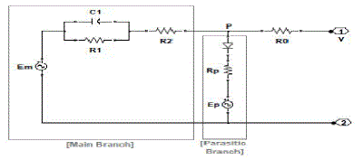
| The structure did not model the internal chemistry of the lead-acid battery directly; the equivalent circuit empirically approximated the behavior seen at the battery terminals. The structure consisted of two main parts: a main branch which approximated the battery dynamics under most conditions, and a parasitic branch which accounted for the battery behavior at the end of a charge. |
| The battery equivalent circuit represented one cell of the battery. The output voltage was multiplied by six, the number of series cells, to model a 12 volt automotive battery. In Figure 3, the number of series cells was entered into the Gain block with parameter value “ns.” The voltage multiplication by six assumed that each cell behaved identically. Figure 4 shows the electrical circuit diagram containing elements that were used to create the battery circuit equations. Each equivalent circuit element was based on nonlinear equations. The nonlinear equations included parameters and states. The parameters of the equations were dependent on empirically determined constants. |
DESIGN OF THREE INPUT BOOST CONVERTER
|
| A. Modes of Operation |
| 1) First Power Operation Mode |
| In this operation mode, two input power sources V1 and V2 are responsible for supplying the load, and battery charging is not done. This operation mode is considered as the basic operation mode of the converter. As clearly seen from the converter structure, there are two options to conduct input power sources currents IL1andIL2 without passing through the battery; path 1: S4− D3 path 2:S3-;D4. In this operation mode, the first path is chosen; therefore, switch S3 is turned OFF while switch S4is turned ON entirely in the switching period. Thus, three different switching states of the converter are achieved in one switching period. |
| Switching state 1 (0 < t <D1T): At t = 0, switches S1and S2 are turned ON and inductors L1 and L2are charged with voltages across V 1and V2 respectively. |
| |
| Switching state 2 (D1T< t <D2T): At t =D1T, switch S1; is turned OFF, while switch is S2;still ON. Therefore, inductor L1 is discharged with voltage across V1-V0 into the output load and the capacitor through diode D1 while inductor L2 is still charged by voltage across V2. |
| Switching state 3 (D2T < t < T): At t = D2 T, switch S2 is also turned OFF and inductor L2 is discharged with voltage acrossV2 V0 as like as inductor |
| By applying voltage–second and current–second balance theory to the converter, following equations are obtained: signals of the four switches |
 |
| 2) Second Power Operation Mode |
| In this operation mode, two input power sourcesV1 and V2along with the battery are responsible for supplying the load. Therefore, discharging state of the battery should be provided in this operation mode. Referring to the converter topology, when switches S3;nd S4 are turned ON simultaneously, currentsIL1 and IL2are conducted through the path of switch S4.Switch S3 hich results in battery discharging. However, discharging operations of the battery can only last until switches S3 and S2 are conducting. As a result, the maximum discharge power of the battery depends on duty ratios of D1 and D2 as well as currents IL1 andIL2. |
| Switching state 1 (0 < t <D4T): At t = 0, switch S1 and S4 are turned ON, so inductors L1and are charged with voltages across V1 and V2, respectively . |
| Switching state 2: At t = are still ON. Therefore, inductors and L charged with voltages across respectively. |
| Switching state 3 (D T< t < DT): At t = T, switch inductor L is discharged with voltage across V while inductor L is still charged with voltages across V. |
| Switching state 4 At t = is also turned OFF and inductors and are discharged with voltage across respectively. |
| By applying voltage–second and current–second balance theory to the converter, following equations are obtained. |
 |
| 3) Third Power Operation Mode |
| In this operation mode, two input power sources V1 and V2 are responsible for supplying the load while the battery charging performance is accomplished. Therefore, the charging state of the battery should be provided in this operation mode. Referring to the converter topology, when switches S4are turned OFF, by turning ON switches S1 andS2currents IL1;nd IL2are conducted through the path of diodeD4,the battery and diod eD3Therefore, the condition of battery charging is provided. However, the charging operation of the battery can only last until switches S3 and S2 are conducting. As a result, the maximum charge power of the battery depends on duty ratios D1 and D2 in order to acquire a desired maximum charge power of the battery, the input power sources should be designed in proper current and voltage values. On the other hand, regulating the charging power of the battery below the P max bat.ch can be made by changing the state of only one of switches S3 and S4 before switches S3 and S2 are turned OFF. |
| Switching state 2 (D3T < t < D1T): At t = D3T, switch S3 is turned OFF while switches S1and S2are still ON (according to the assumption). Therefore, inductors L1 and L2 are charged with voltages across V1 and V2 , respectively . Switching state 3 (d1 T < t < d2 T): At t = D1T, switch S1is turned OFF, so inductor L2 is discharged with voltage across V1 − V0 , while inductor L1 is still charged with voltage across V2. |
| Switching state 4 (D2T< t < T): At t = D2T, switch S2 is also turned OFF and inductor L2 as like as L1 is discharged with voltage across V2-V0 |
 |
SIMULATION RESULT
|
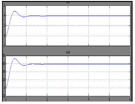
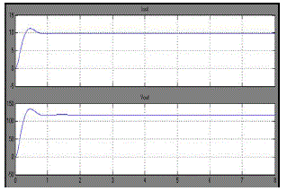
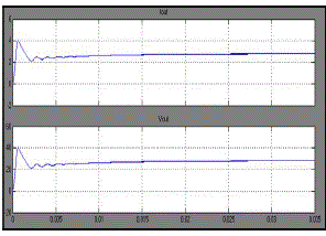
| The following figure shows that output waveform of the three input boost converter. Figure 3(a) shows the solar voltage and current. Using this converter the voltage level and current level are boost the input voltage levels. To increase the voltage levels the number cells are connected in series also increase. Figure 3(b) shows the wind generator output voltage and current. Figure3(c) shows the output voltage of the battery. |
CONCLUSION
|
| Renewable energy sources conjointly referred to as non-conventional approach of energy area unit ceaselessly replenished by natural processes. With the merits of flexibility, the proposed three input converter shows excellent performance and potential for various applications including communication systems, satellite, radar systems. In comparison with the conventional method of hybridizing three input sources with three-boost cells the proposed converter can economize in the number of inductors, makes use of low-voltage batteries or super capacitors, works in high-stablemargin operating points and gain access to high-voltage boost factor. the battery can be charged and discharged through the both power sources individually and simultaneously. Three input boost converter advantages are Simple structure, lowpower components, centralized control, no need to transformer, low weight, high-stability working point, independent operation of input power sources, and high level of boosting. |
Figures at a glance
|
 |
 |
 |
 |
 |
| Figure 1 |
Figure 2 |
Figure 3a |
Figure 3b |
Figure 3c |
|
References
|
- H. Krishnaswami and N. Mohan, “Three-port series-resonant DC–DC converter to interface renewable energy sources with bidirectional load andenergy storage ports,” IEEE Trans. Power Electron., vol. 24, no. 10, pp. 2289–2297, Mar. 2009.
- H. Tao, A. Kotsopoulos, J. L. Duarte, and M. A. M. Hendrix, “Family of multiport bidirectional DC–DC converters,” in Proc. IEE Elect. Power Appl.,2006, pp. 451–458.
- M. Sarhangzadeh, S. H. Hosseini, M. B. B. Sharifian, and G. B. Gharehpetian, “Multi-input direct DC–AC converter with high frequency link forclean power generation systems,” IEEE Trans. Power Electron., vol. 26, no. 6, pp. 1777–1789.
- L. Solero, A. Lidozzi, and J. A. Pomilio, “Design of multiple- input power converter for hybrid vehicles,” IEEE Trans. Power Electron., vol. 20, no. 5,pp. 1007–1016, Sep. 2005.
- H. Tao, J. L. Duarte, andM. A.M. Hendrix, “Three-port triple- half-bridge bidirectional converter with zero-voltage switching,” IEEE Trans.PowerElectron., vol. 23, no. 2, pp. 782–792, Mar. 2008.
- R. J.Wai, Ch.Y. Lin, andY. R. Chang, “High step-up bidirectional isolated converter with two input power sources,” IEEE Trans. Ind.Electron.,vol. 56,no. 7, pp. 2629–2643, Jul. 2009.
- Zh. Qian, O. A. Rahman, and I. Batarseh, “An integrated four- port DC/DC converter for renewable energy applications,” IEEE Trans. PowerElectron., vol. 25, no. 7, pp. 1877–1887, Jul. 2010.
|