Keywords
|
| Brushless DC Motor; PI Controller; Sliding Mode Controller. |
INTRODUCTION
|
| The PMBLDC is essentially configured as a permanent magnet rotating part, a set of current carrying conductors. In this respect, it is equivalent to an inverted DC commutator motor, in that the magnet rotates while the conductors remain stationary. In both cases, the current must reverse polarity every time a magnet pole passes by, in order that the torque is unidirectional. In the DC commutator motor, the commutator and brushes perform the polarity reversal. In the brushless DC motor, the polarity reversal is performed by power MOSFETS, which must be switched in synchronism with the rotor position. The stator is normally 3-phase star connected. Each commutation sequence has one of the windings energized to positive power current entering into the winding and the second winding energized to negative power current exits the winding and third winding non-energized. Torque is produced by the interaction of the magnetic field produced by the permanent magnets and the stator windings. [1] |
NOMENCLATURE
|
| va, vb, vc Voltages of phases A, B, C respectively (V) |
| ea, eb, ec Back emfs of phases A, B, C respectively (V) |
| ia, ib, ic Phase currents (A) |
| R Resistance of each phase winding (Ω) |
| Laa, Lbb, , Lcc, Ls Self inductances (H) |
| Lba, Lca, Lbc, M Mutual inductances (H) |
| Te, TL, Tref Electromagnetic, load and refernce torques (N-m) |
| J Moment of inertia of rotor (Kg-m2) |
| B Viscous friction coefficient (Nm-sec/rad) |
| θ Angular position of the rotor (rad) |
| ωr,ωref ref Actual rotor speed, reference speed (rad/s) |
| ψar Flux linkage on rotor |
| λa Flux linkage of the phase A |
| Kp, Ki Proportional and Integral gains of the PI controller |
| Kt Torque constant |
| δ Total disturbance |
MODELLING OF PMBLDC MOTOR
|
| The voltage equation of one phase of PMBLDC motor given by |
 |
| In balanced three-phase PMBLDC motors |
 |
 |
 |
| Combining equations (1) and (2) |
 |
| where (L = Ls – M) |
| The last term in the equation (3) is the back EMF ea, and the term is redefined and per phase voltages expressed as |
 |
| It is seen that ψar (θ) in equation (3) is expressed as a constant value times a flux linkage function that is changed only by the rotor position as shown in equation (4). The far(θ) is a flux linkage form function that is a function of rotor position. [2,3] The phase current flowing through each winding can be obtained from equation (3). |
| The phase current flowing through each winding can be expressed as follows |
 |
 |
 |
| |
| The line-to-line voltage equations are used as follows: |
 |
 |
| where ω stands for the instantaneous speed. The fabr(θ) is a line-to-line flux linkage form function that is a function of the rotor position. Now we define a new function, H(θ)ab, as |
 |
| Then, H(θ)ab can be derived as |
 |
| Since the H(θ)ab function itself has a one to one relationship with rotor position, it is possible to use this function for position estimation. But as shown in eq.(4.14), to know the H(θ)ab function, the instantaneous speed term, that is unknown for dynamic operations, is required to calculate the function. |
| To eliminate the instantaneous speed term, ω that causes trouble in using the H(θ)ab function for position estimation, one line- to-line H(θ) function is divided by another line-to- line H(θ) function, and the divided new speed independent function is named G(θ). |
 |
| The electromagnetic torque developed is |
 |
| The torque balance equation is expressed as |
 |
| The rotor speed ωr is expressed as |
 |
| The rotor position at each mode can be estimated by using Table 1. |
PI CONTROLLER
|
| PI controller operates the PMBLDC motor at the set point corresponding to a reference speed. It is important to incorporate a controller in the feedback path. The PI controller contains an outer speed controller and an inner current controller. Accordingly a PI speed controller has been chosen with gain parameters Kp and Ki. The speed of the PMBLDC motor compared with the reference value and the error in speed is processed by the speed controller. [4] |
| The output of the PI controller at any instant is the reference torque given by |
 |
SLIDING MODE CONTROLLER
|
| The sliding mode controller modelling approach involves two distinct stages. The first stage considers the modelling of a switching function which provides desirable system performance in the sliding mode. The second stage consists of modelling a control law which will ensure the sliding mode, and thus the desired performance, is attained and maintained. With sliding mode controller, the system is controlled in such a way that the speed error in the PMBLDC motor always moves towards a sliding surface.[5,6] The sliding surface is defined with the tracking speed error of the motor and its rate of change of variables. The distance of the error trajectory from the sliding surface and its rate of convergence are used to decide the control input to the motor. The sign of the control input must change at the intersection of the tracking error trajectory with the sliding surface. In this way the error trajectory is always forced to move towards the sliding surface. [7,8] |
| The equation (17) is rewritten as |
 |
where  |
| Δa ,Δb,Δc represent the transient or disturbance values of the machine parameters J, B and Kt respectively The state variable is defined as |
 |
| For step changes in speed reference, substituting equation (12) into equation (10), we get |
 |
| where the total disturbance ïÃÂä is defined as |
 |
| The design of the sliding mode controller includes the selection of sliding surface and the control law. Once the system states enter the sliding mode, the system dynamics is determined by the chosen sliding surface and is robust to the disturbances as well as parameters variations. The control law must satisfy the reaching condition and guarantees the existence of the sliding mode.[9] Since SMC is applicable to the first-order system, the SMC employs the acceleration signal, which is sensitive to the noises. |
PMBLDC MOTOR DRIVE WITH SM CONTROLLER
|
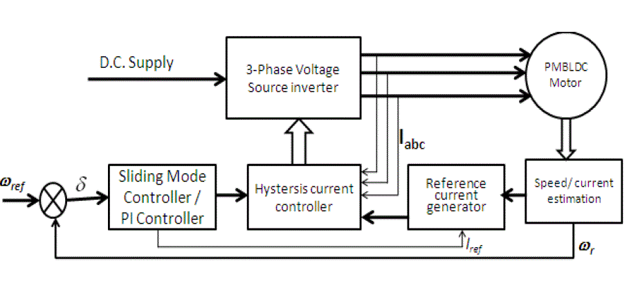
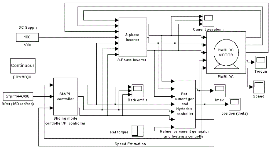
| The general block diagram of the SM controlled drive of the permanent magnet brushless dc motor is shown in Fig. 1. The complete drive system of a PMBLDC motor consists of a permanent magnet motor fed by a three-phase PWM inverter, rotor position estimation and SM controller. The inverter which is connected to the dc supply feeds controlled power to the motor. The magnitude and frequency of the inverter output voltage depends on the switching signals generated by the hysterisis controller.[10]. The state of these switching signals at any instant is determined by the rotor position, speed error and winding currents. The controller synchronizes the winding currents with the rotor position. It also facilitates the variable speed operation of the drive and maintains the motor speed reference value even during load variations and supply fluctuations. [11]. The simulink diagram of PI controller and SM controller is shown in Fig. 2 |
SIMULATION AND ANALYSIS OF RESULTS
|
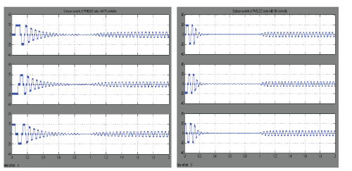
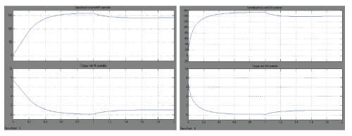
| The motor is started at no-load and reference speed is set at 150 rad/sec at no load . Load torque of 1 Nm is applied after 1 sec. The motor is rated at 100 V, 2 Nm and 136 rad/sec. The results of PMBLDC motor with PI and SM controllers are compared. The variation of current, speed, and torque are shown in Fig. 3 and Fig. 4. |
| The current waveform are shown in the Fig. 3 (a) and Fig. 3 (b)respectively. The initial peak current is 20 A for both the controllers. In PI controller, the initial current oscillations are more and subsided after 0.9 sec. But in SM controller the oscillations are less and subsided after 0.45 sec only. After load is applied the rms value of current with PI controller is 3.8 A and with SM controller is 3.5 A. Also there is a low frequency oscillations of current during starting with SM controller. |
| The speed and torque waveforms are shown in the Fig. 4 (a) and Fig. 4 (b). For PI controller and SM controller the initial acceleration at starting are 500 rad/sec2 and 1500 rad/sec2 respectively and final speed before application of load are 156 rad/sec and 152 rad/sec respectively. It is seen that the initial acceleration in SM controller is 3 times higher than that of PI controller. Thus, the speed error are 4 % for PI controller and 1.3 % for SM controller. The torque at starting is 7.5 Nm with PI controller and 6.5 Nm with SM controller. Also the torque response is faster in the latter case. The steady-state torque of 1 Nm is reached in 0.6 sec with PI controller and with SM controller is 0.4 sec. |
CONCLUSION
|
| In this paper the sliding mode controller is modelled, for PMBLDC motor are organized so as to apply the SM control technique. Considering the case such as starting time and at application of load.. It also gives good trajectory tracking performance. the responses of current, speed and torque with SM controller is superior than with PI controller.. The SM controller is simulated under transient conditions and a comparative study of the results with that of PI controller has been presented and proved that SM controller has better performance in all aspects. |
Tables at a glance
|
 |
| Table 1 |
|
Figures at a glance
|
 |
 |
 |
 |
| Figure 1 |
Figure 2 |
Figure 3 |
Figure 4 |
|
References
|
- Miller T.J.E and Hendershot Jr. J.R (1994), Design of brushless Permanent Magnet Motors, Magna Physics Publishing and Clarendon press,Oxford.
- PragasenPillay and R. Krishnan, Modeling, Simulation, and Analysis of Permanent Magnet Motor Drives, Part-II: The Brushless DC MotorDrive, IEEE Trans.on Industry Application, Vol.25, No.2, pp.274-279, March/April1989.
- Tae-Hyung Kim and MehrdadEhsani, Sensorless Control of the BLDC Motors From Near-Zero to High Speeds, IEEE Trans.PowerElectronics, Vol. 19, No. 6, November 2004.
- Vadim I. Utkin, “Sliding mode control design principles and applications to electric drives,” IEEE Transactions on Industrial Electronics,vol.40, no.1, pp23-36, February 1993.
- Hailong Song, Young Yu, Ming Yang , DianguoXu, A Novel SMC-Fuzzy Speed Controller for Permanent Magnet Brushless DC Motor,IEEE, pp.281-285, 2003.
- Jessen Chen and Pei-Chong Tang, A sliding mode current control scheme for PWM brushless DC motor drives, IEE Proc.-Electr. PowerAppll.,vol.14, no.3, pp.541-551, May, 1999.
- xiachangliang, "BLDC motor control system," M. Science press. Feb.2009. pp.80-82.
- Yuan zhaohui, Lin weizhong, "Fuzzy Sliding Mode Control Based on Genetic Algorithm for Brushless DC Motor, " Small &SpecialElectrical chines, Feb.2009, pp. 43-46.
- J. Chen and P.-C. Tang, “A sliding mode current control scheme for PWM brushless DC motor drives,” IEEE Trans. Power Electronics,vol.14, no.3, pp. 541–551, May, 1999.
- Chee-MunOng, Dynamic Simulation of Electric Machinery using MATLAB/Simulink , 1998.
- http://www.mathworks.com.
|