Keywords
|
| Bearing current, common mode voltage, induction motor drive, multilevel inverter, SPWM. |
INTRODUCTION
|
| The phenomenon of bearing currents in induction motors has been known for decades. It has been reported by Alger [1] in the 1920âÃâ¬ÃŸs that the basic reason for these currents is asymmetric flux distribution inside of the motor .This problem has been effectively solved with modern motor designing and manufacturing practices. However, unexpectedly the problem has returned since power electronic devices are becoming common in Adjustable Speed Drives (ASDs). PWM inverters with IGBT operate at switching frequencies of 2 to 20 kHz and rise time of 0.1μsec with voltage rise of 6000V/μsec for 400V system. The high dv/dt has adverse effects on bearing damage caused by bearing currents due to common mode voltage [3]-[6]. |
| The bearing current faults are most frequent in PWM fed ASDs, nearly 30% according to an IEEE motor reliability studies. The bearing currents cause premature bearing failure within 1-6 months of installation. In order to protect ASD investment, predictive maintenance is highly recommended for early detection and schedulable replacement of defective bearing to avoid the hidden costs involved in downtime and lost product. |
| There are mainly two types of inverter induced bearing currents: |
| i) Electric Discharge Machining (EDM) bearing current: An electrically insulated lubrication film normally has thickness ranging from 2-3 microns, the bearing voltage Vb mirrors the common mode voltage Vcom at the stator terminals via capacitor voltage divider i.e Bearing Voltage Ratio (BVR).The electrically loaded oil film between balls and races breaks down when threshold voltage of the film exceeds dielectric strength of lubricating oil of about15Vpk/μm (approx.5-30V) ,thereby causing the EDM current pulses and results in premature bearing failure [2]. |
| ii) High frequency circulating bearing current: The high dv/dt at the motor terminals causes mainly because of the stator winding to frame capacitance ( Csf) a part of an additional HF common mode current Ib=Csf dVcom/dt. The ground current excites a circular magnetic flux around the shaft of the motor (circulating bearing current).If shaft voltage is large enough to puncture the lubricating film of the bearing and destroy its insulating properties, it causes a circulating bearing current in the loop „ stator frame—non-drive end—shaft—drive endâÃâ¬ÃŸ. Peak amplitude varies depending on the motor size [2]. |
| ii) High frequency circulating bearing current: The high dv/dt at the motor terminals causes mainly because of the stator winding to frame capacitance ( Csf) a part of an additional HF common mode current Ib=Csf dVcom/dt. The ground current excites a circular magnetic flux around the shaft of the motor (circulating bearing current).If shaft voltage is large enough to puncture the lubricating film of the bearing and destroy its insulating properties, it causes a circulating bearing current in the loop „ stator frame—non-drive end—shaft—drive endâÃâ¬ÃŸ. Peak amplitude varies depending on the motor size [2]. |
| The paper is organized as follows: Section I gives introduction about bearing currents, its causes, types and various mitigation techniques. Section II deals with common mode voltage and multilevel inverters helps to understand background of related work and simulink modeling. Section III explains simulink modeling of inverter, HF induction motor with common mode equivalent circuit. Section IV shows the simulation results .Section V includes the conclusion about the paper and followed by reference and bibliography. |
COMMON MODE VOLTAGE AND MULTILEVEL INVERTER
|
| A. Common Mode Voltage |
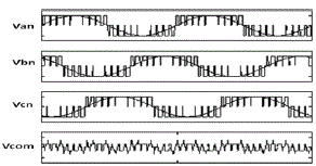
| At the PWM inverter output, instantaneous summation of all the three phase voltages is non zero, an average voltage in a neutral point w.r.t ground create so called common mode voltage. |
 |
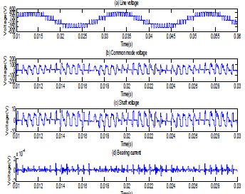
| In which Van, Vbn and Vcn are the phase voltages generated by the PWM inverter. The common mode voltage is a stair case function of amplitude equal to the DC bus voltage and the frequency equal to the inverter switching frequency. The waveform of common mode voltage is schematically shown in Fig 2. |
| The shaft voltage has the same shape as the common mode voltage, because the shaft voltage is formed as a result of common mode voltage and capacitive voltage divider circuit. The source of common mode voltage at the output of inverter is the cause of a voltage emerging on shaft, because of the distribution of parasitic capacitances inside of the motor. These create an internal capacitive divider and the BVR can be expressed as in [3][4]. |
 |
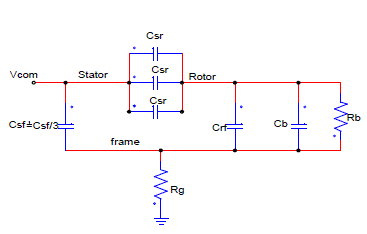
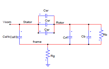
| Where ,Vsh is shaft voltage ,Csr is capacitance between stator winding and rotor, Crf is capacitance between stator frame and rotor or air gap capacitor ( Cg), C b is bearing capacitance .The ratio Vsh /Vcom is typically in the range of 1:10 because the value of the Cg is much larger than that of Csr. The Csr value is small when compared with other capacitances because of the relatively large distance and small area between stator and rotor. However it has significant influence on the value of BVR .Fig .3.Shows the common mode equivalent circuit with various parasitic capacitances in an AC motor that become relevant when the motor is driven by PWM voltage source inverter [3][4]. |
| C. Multilevel Inverter |
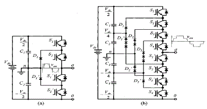
| Several multilevel inverter topologies and modulation technologies have been developed and applied to high power and high voltage systems. The main advantages of multilevel inverter topologies is the reduction of voltage stress on the semi conductor devices used in the inverter bridge and the generation of high quality output voltages. They generate smaller Common-Mode (CM) voltage, thus reducing the stress in the motor bearings. In addition, using sophisticated modulation methods, CM voltages can be eliminated [8]. Presently there are three kinds of multilevel inverters: (1) Neutral Point Clamped inverter (NPC) (2) Flying Capacitor inverter and (3) Cascaded inverter. This paper presents modeling and simulation analysis of neutral point clamped multilevel inverter fed induction motor drive using SPWM technique. |
SIMULINK MODELLING
|
| This paper presents modeling and simulation of 2-level and diode clamped multilevel inverter fed induction motor drive using Mat lab/Simulink software. The output voltages of the inverters have been recorded and analyzed for its harmonic contents.PWM signals are generated using a high frequency triangular wave, called the carrier wave, is compared to a sinusoidal signal representing the desired output, called the reference wave. Whenever the carrier wave is less than the reference, a comparator produces a high output signal, which turns the upper switch in one leg of the inverter ON the lower switch OFF. In the other case the comparator sets the firing signal low, which turns the lower switch ON and upper switch OFF [10].Simulink model also includes common mode equivalent circuit with bearing model for measurement of shaft voltage and bearing current. |
| A. Modeling of High Frequency Induction Motor and Common Mode Equivalent Circuit. |
| The induction motor used in this paper is a 2.2kW (3hp) , fed from a three-phase PWM Inverter using V/Hz to control the motor speed. The induction motor equivalent electrical circuit parameters are determined by two wattmeterâÃâ¬ÃŸs method i.e. no-load and the blocked-rotor tests. These tests were performed at the frequency of 50Hz [7]. Induction motor specification: rated power: 3Hp (2.2kW), rated Voltage: 440V/50Hz (Δ), pole number: 4, rated current: 5A , rated speed: 1500 rpm. |
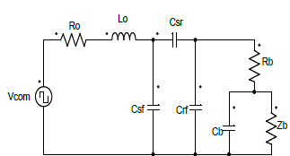
| Inverter specification: 2.2kW, switching frequency:2 kHz, output frequency:50Hz, sine triangle PWM modulation technique is used. Table I shows the results for the no-load and blocked rotor tests. The equivalent electrical circuit parameters are determined (per phase) and presented in the in Table II. Fig.4. Shows the per phase equivalent circuit used in the simulation. |
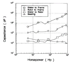
| The values of parasite capacitances of the induction motor are obtained from curves shown in Fig.7.The capacitance variations as a function of the motor H.P rating and from the capacitance characteristic equations presented as in [4][5] .Which show that these parasite capacitances are dependent only on the physical and constructive characteristic of the motor according to Fig.8. |
| Electrical circuit is drastically simplified as it can be seen impedance between stator winding and rotor Zsr for frequencies under 200 kHz has capacitive behavior and impedance between stator winding and stator frame Zsf is a series RC circuit. Under the inverter switching frequencies the motor parasite impedances have pure capacitive characteristic, so the high frequency induction motor electrical equivalent circuit gets simplified as shown in Fig.5[7]. |
| B. Simulink Model |
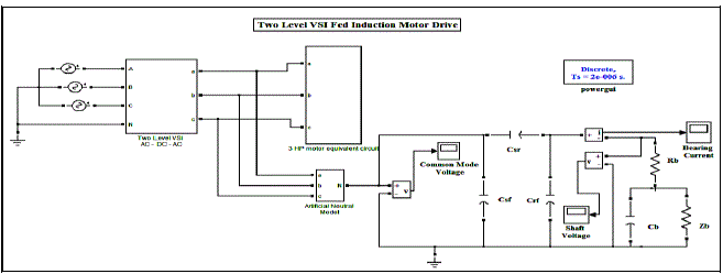
| Fig.7 shows the complete Simulink model of 2-level SPWM inverter fed induction motor drive implemented using MATLAB /Simulink. Similarly for diode clamped multilevel inverters (3,5and7level) fed induction motor drive is implemented. The inverter switching frequency is 2 kHz and the output frequency is 50Hz. |
SIMULATION RESULTS
|
CONCLUSION
|
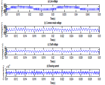
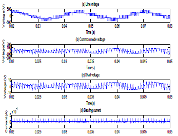
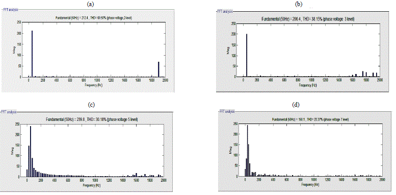
| In this paper modeling and simulation analysis of the shaft voltage and bearing current for SPWM 2-level and diode clamped multilevel inverters fed induction motor has been presented. A simplified high frequency modeling of induction motor and common-mode equivalent circuit is carried out. It is observed from simulation results , common mode voltage, shaft voltage, bearing current and %THD reduction with 3, 5 and 7 level inverter fed induction motor compared to 2-level inverter fed induction motor. Hence reduction in common mode voltage, shaft voltage, bearing current and harmonics increases the life of the motors as well as reduces many more hidden problems in the motors. |
Tables at a glance
|
|
|
Figures at a glance
|
 |
 |
 |
 |
| Figure 1 |
Figure 2 |
Figure 3 |
Figure 4 |
 |
 |
 |
 |
| Figure 5 |
Figure 6 |
Figure 7 |
Figure 8 |
 |
 |
 |
 |
| Figure 9 |
Figure 10 |
Figure 11 |
Figure 12 |
|
References
|
- Alger P., Samson H., "Shaft Currents in Electric Machines" A.I.R.E. Conference ., Feb. 1924
- Annette Muetze, Andreas Binder, “Techniques for Measurement of Parameters Related to Inverter Induced Bearing Currents” ,IEEE transactions on industryapplications,vol.43,No5,September/October2007.
- J. Erdman, R. J. Kerkman, D. Schlegel, and G. Skibinski, “Effect of PWM inverters on AC motor bearing currents and s haft voltages,” IEEE , An AppliedPower Electronics Conference and Exposition,vol.1, pp. 24 -33. Mar. 5-9, 1995.
- Doyle Busse, Jay Erdman, Russel J. Kerkman, Dave Schlegel, and Gary Skibinski, “System Electrical Parameters and Their Effects on Bearing Currents”,IEEE transactions ISBN 0-7803-3044-719, 1996.
- D. Busse, J. M. Erdman, R. J. Kerkman, D. W. Schlegel, and G. L. Skibinski, “Bearing currents and their relationship to PWM drives,” IEEE IECON ’95,Nov. 1995.
- A Muetze, A. Binder, “Calculation of motor capacitances for prediction of discharge bearing currents in machines of inverter-based drive systems,”Proceedings of the 5th International Electric Machines and Drives Conference (IEMDC), San Antonio, TX. pp. 264-270.May 15- 18, 2005.
- Rudolf RibeiroRiehl and Ernesto RuppertFilho,”A Simplified Method for Determining the High Frequency Induction Motor EquivalentElectrical Circuit Parameters to be Used in EMI Effect”.Proceeding of International Conference on Electrical Machines and Systems, Seoul, Korea . pp .1244-1248. Oct 8-11, 2007.
- José Rodríguez, Jih-Sheng Lai, Fang ZhengPeng, “Multilevel Inverters: A Survey of Topologies, Controls, and Applications”. IEEE transactions on industrialelectronics, vol. 49, no. 4, pp. 724-734.August 2002.
- Annette von Jouanne, Haoran Zhang, Alan K. Wallace“, An Evaluation of Mitigation Techniques for Bearing Currents, EMI and Overvoltage in ASDApplications ”. IEEE transactions on industry applications, vol. 34, no. 5 .pp. 1113-1122. September /October 1998.
- Haoran Zhang , Annette von Jouanne, Shaoan Dai, Alan K. Wallac, “ Multilevel Inverter Modulation Schemes to Eliminate Common-Mode Voltages”. IEEEtransactions on industry applications,vol.36,no.6.pp.1645-1653.November/December 2000
|