Keywords
|
| Multilevel Inverter, Torque Developed, SRM, Modulation Techniques. |
INTRODUCTION
|
| The growing interest in switched reluctance machines (SRMs) for automotive and industrial applications leadsto the study and modeling of SRM. The switched reluctance generator (SRG) is an energy conversion device that has advantages in both renewable and alternative transportation systems. With the absence of excitation on the rotor, the SRG provides a robust, compact and efficient generator system. The absence of permanent magnet in the machine is a big cost and material availability is the advantage over the other permanent magnet machines. The nonlinear behavior of the SRG poses a good challenge to the control of the machine. This paper addresses and mitigates the complexities of torque developed so that the advantage of SRG can be utilized effectively. |
| Numerous industrial applications require higher power apparatus in recent years. Some medium voltage motor drives and utility applications require medium voltage and megawatt power level. For a medium voltage grid, it is troublesome to connect only one power semiconductor switch directly. As a result, a multilevel power converter structure has been introduced as an alternative in high power and medium voltage situations subsequently; several multilevel converter topologies have been developed. A multilevel converter not only achieves high power ratings, but also enables the use of renewable energy sources. The term multilevel began with the three-level converter. The advantages of three-level Inverter topology over conventional two-level topology are 1)The voltage across the switches is only one half of the DC source voltage 2)The switching frequency can be reduced for the same switching losses 3)The higher output current harmonics are reduced by the same switching frequency. The modulation methods used in multilevel inverters can be classified according to the switching frequency. They are 1) Sinusoidal PWM 2) Selective Harmonic Elimination 3) Space Vector PWM. The existing system uses the Sinusoidal PWM |
| Technique to control the total harmonic distortion. Fig.1 shows the block diagram of SRG system connected to the battery forcharging |
SINUSOIDAL PULSE WIDTH MODULATION (SPWM)
|
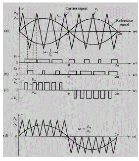
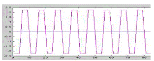
| In sinusoidal PWM instead of maintaining the width of all pulses the same as in the case of multiple PWM, the width of each is varied in proportion to the amplitude of a sine wave evaluated at the same pulse. The distortion is reduced significantly compared to multiple PWM (Figure 2). |
| The number of pulses per half cycle depends on the carrier frequency. Within the constraint that two transistors of the same arm cannot conduct at same time, the instantaneous output voltage. This method is preferable and easier to implement. The output voltage can be varied by varying the modulation index ‘m’. The area of each pulse corresponds approximately to the area under the sine wave between the adjacent mid points of off-periods on the gating signals. |
| Five level cascaded H bridge inverter voltage level and its switching states: |
 |
 |
MATHEMATICAL MODELING OF SRM
|
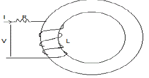
| The mathematical modeling of Switched Reluctance Motor is derived using the basic voltage equation. And by using the voltage equation, the torque equation is derived. |
| BASIC VOLTAGE EQUATION OF SRM |
| From Fig. |
 |
| Where ψ is a function of θ and L |
| iR is the ohmic drop |
 |
 |
| L di/dt –Emf due to incremental inductance |
| i(w)dL/dθ– Self-induced Emf or e |
 |
| Self-induced Emf e is proportional to current speed and rate of change inductance with rotor angle. |
| DERIVATION FOR TORQUE EQUATION OF SRM: |
| On the basis of the magnetic circuit theory, the stored energy in a magnetic field |
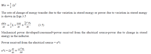 |
| Power due to change in stored energy |
 |
| Mechanical power developed |
 |
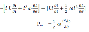 |
| Eqn 3.9 is known as Mechanical Power Equation. |
| Pm = ωT |
Where  |
 |
Torque developed in SRM  |
SIMULATION & RESULTS
|
| Fig.a shows the graph between various rotor positions Vs. Inductance. |
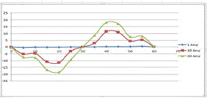 |
| Fig. b shows torque profile and it is between various rotor positions and current |
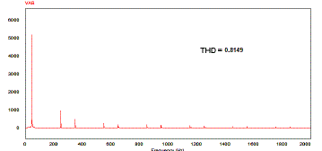 |
| Normalized harmonic amplitude of the voltage waveform of two-level inverter with fundamental frequency of 50Hz |
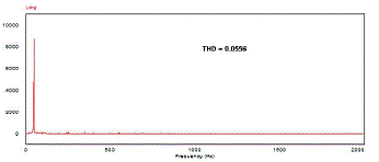 |
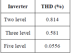
| Tabulation for THD values |
 |
RESULTS AND DISCUSSIONS
|
| The main aim of any modulation technique is to obtain variable output having maximum fundamental component with minimum harmonics. The objective of Pulse Width Modulation techniques is enhancement of fundamental output voltage and reduction of harmonic content in three level and Five level Cascaded H- Bridge Inverter. In this paper usage of Switched Reluctance Motor has been enhanced. |
Figures at a glance
|
 |
 |
 |
 |
| Figure 1 |
Figure 2 |
Figure 3 |
Figure 4 |
|
References
|
- SandeepNarla, YilmazSozer, Iqbal Husain (2012) ‘Switched Reluctance Generator Controls for Optimal Power Generation and BatteryCharging’ IEEE, Transactions on Industry Applications, Volume 48, No.5, pp. 43-53.
- X.D. Xue, K.W.E. Cheng, Y.J. Bao, P.L.Leung, and N. Cheung (2012) ‘Switched Reluctance Generators with Hybrid Magnetic Paths forWind Power Generation’ IEEE, Transactions on Magnetics, Volume 48, No.11, pp. 102-112
- David A. Torrey (2002) ‘Switched Reluctance Generators and their Control’ IEEE, Transactions on Industrial Electronics, Volume 49, No.1,pp. 57-67
- O.Ichinokura, T.Onda, M.Kimura, T.Watanabe, T.Yanada, and H.J.Guo (2000) ‘Analysis of Dynamic characteristics of Switched ReluctanceMotor Based on SPICE’ IEEE, Transactions on Magnetics, Volume 34, No.4, pp. 86-96
- Christos Mademlis and IordanisKioskeridis (2005) ‘Optimizing Performance in Current – Controlled Switched Reluctance Generators’ IEEE,Transactions on Energy Conversion, Volume 20, No.3, pp. 89-99
- Yuan-Chihchang and Chang-Ming Liaw (2008) ‘On the Design of Power Circuit and Control Scheme for Switched Reluctance Generator’IEEE, Transactions on Power electronics, Volume 23, No.1, pp. 44-54
- Osamu Ichinokura, Tsukasa Kikuchi, Kenji Nakamura, Tadaaki Watanabe, Hai-Jiao (2003) ‘Dynamic Simulation Model of SwitchedReluctance Generator’ IEEE Transactions on Magnetics, Volume 39, No.5, pp 99-101
- Christophe Roux an MedhatM.Morcos (2002) ‘On the Use of a Simplified Model for Switched Reluctance Motors’ IEEE Transactions onEnergyConvesion, Volume 17, No.3, pp. 110-120
- A.Takahashi, H.Goto, K.Nakamura, T.Watanabe, O.Ichinokura (2006) ‘Characteristics of 8/6 Switched Reluctance Generator excited bySuppression Resistor Converter’ IEEE Transactions on Magnetics, Volume 42, No.10, pp. 76-86
- IodanisKioskeridis, Christos Mademlis (2006) ‘Optimal Efficiency Control of Switched Reluctance Generators’ IEEE Transactions onPower Electronics, Volume 21, No.4, pp. 56-66
|