Keywords
|
| Modular Multilevel converters, voltage-balancing control, Multi Carrier Pulse Width Modulation. |
INTRODUCTION
|
| High-power converters for utility applications require line-frequency transformers for the purpose of enhancing their voltage or current rating [1]–[4]. The 80-MVA Static synchronous Compensator (STATCOM) commissioned in 2004 consists of 18 neutral-point-clamped (NPC) converter legs [4], where each of the ac sides is connected in series by the corresponding transformer. The use of line-frequency transformers, however, not only makes the converter heavy and bulky, but also induces the so-called dc magnetic flux deviation when a single-line-to-ground fault occurs [5]. Recently, many scientists and engineers of power systems and power electronics have been involved in multilevel converters intended for achieving medium-voltage power conversion without transformers [6]–[8]. Two of the representatives are: |
| 1) The diode-clamped multilevel converter (DCMC) [6], [7]; |
| 2) The flying-capacitor multilevel converter (FCMC) [8]. |
| The three-level DCMC or a NPC converter [9] has been put into practical use [10]. If a voltage-level number is more than three in the DCMC, inherent voltage imbalance occurs in the series-connected dc capacitors, thus resulting in requiring an external balancing circuit (such as a buck–boost chopper) for a pair of dc capacitors [11]. Furthermore, a significant increase in the clamping diodes required renders assembling and building of each leg more complex and difficult. Thus, a reasonable voltage-level number would be up to five from a practical point of view. |
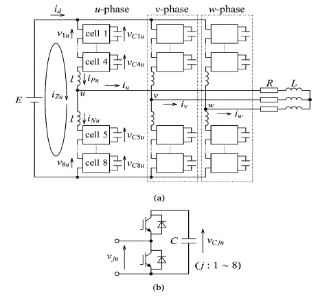
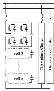
| As for the FCMC, the four-level pulse width modulation (PWM) inverter is currently produced by one manufacture of industrial medium-voltage drives [12]. However, the high expense of flying capacitors at low carrier frequencies (say, lower than 1 kHz) is the major disadvantage of the FCMC [13].A modular multilevel converter (MMC) has been proposed in [14]–[20], intended for high-power applications. Fig. 1 shows a basic circuit configuration of a three-phase modular multilevel inverter. |
| Each leg consists of two stacks of multiple bidirectional cascaded chopper-cells and two non coupled buffer inductors. The MMC is suitable for high- or medium-voltage power conversion due to easy construction/assembling and flexibility in converter design. Siemens has a plan of putting it into practical use with the trade name of “highvoltage direct current (HVDC) - plus.” It is reported in [19] that a system configuration of the HVDC-plus has a power rating of 400 MVA, a dc-link voltage of ±200 kV, and 200 cascaded chopper cells per leg. The authors of [14]–[20], however, have made no detailed description of staircase modulation, especially about a crucial issue of how to achieve voltage balancing of 200 floating dc capacitors per leg. Moreover, no experimental result has been reported yet. |
| This paper focuses on voltage-balancing control and operating performance of a pulse width-modulated MMC (PWMMMC) The final aim of this paper is to apply the PWM-MMC to medium-voltage power converters in a power rating of 1–10 MVA, a dc-link voltage of 10–30 kV, and a switching frequency of 200–2000 Hz. Balancing control enables achievement of voltage balancing of multiple floating dc capacitors without any external circuit. In addition, this paper proposes the closed loop connection of MMC for low-voltage large-current power conversion. Each dc side of positive and negative chopper-cells possesses a common dc capacitor, whereas its ac side is connected in parallel via multiple buffer inductors. The similarity between the two MMCs exists in terms of circuit configuration and control method. |
TOPOLOGIES OF MMCS
|
A. Classification from the Topologies
|
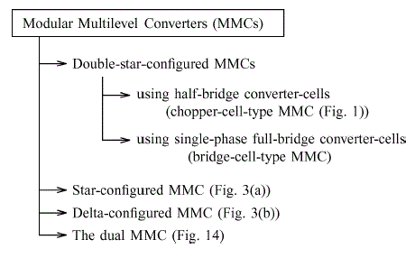
| Fig. 2 shows a classification of MMCs based on single-phase half-bridge or full-bridge converter-cells. From their topologies, MMCs can be classified into: |
| 1) Double-star-configured MMCs; |
| 2) A star-configured MMC [Fig. 3(a)]; |
| 3) A delta-configured MMC [Fig. 3(b)]; and |
| 4) The dual MMC (Fig. 14). |
| Moreover, the double-star-configured MMCs can be classified into: |
| 1) A chopper-cell-type MMC (Fig. 1); and |
| 2) A bridge-cell-type MMC. |
| that the star/delta-configured MMC topology is not applicable to industrial motor drives, but it is suitable for STATCOMs and energy storage systems [21]–[23]. This consideration is one of the most significant differences in function and application between the double-star-configured MMC topology in Fig. 1 and the star/delta-configured MMC topology in Fig. 3.The bridge-cell-type MMC replaces the chopper cell in Fig. 1(b) with single-phase full-bridge converter cells. Hence, the dc-voltage source E can be replaced with a single-phase ac-voltage source [16]. The detail of the dual MMC is discussed in Section V. In this paper, the chopper-cell-type MMC is referred to simply as “the MMC” because attention is paid to it exclusively. |
| C. Definition of DC Loop Currents |
| Fig. 1 shows a three-phase inverter based on the MMC. Each leg of the circuit consists of two stacks of four bidirectional chopper-cells and two non coupled buffer inductors. Each chopper-cell consists of a floating dc capacitor and two insulated-gate bipolar transistors that form a bidirectional chopper. Attention is paid to the u-phase choppercells because the operating principle is identical among the three legs. |
| The following circuit equation exists in Fig. 1(a) 1: |
 |
| Here, E is a supply dc voltage, vju is an output voltage of the u phase chopper-cell numbered j, l is a buffer inductance and iPu and iNu are positive- and negative-arm currents, respectively. The Kirchhoff’s voltage law (KVL) loop given by (1) is referred to as the “dc loop,” which is independent of the load. The circulating current along the uphase dc loop, iZu can be defined as, |
 |
| Note that iP u, iNu, iu, and id are branch currents whereas iZu is a loop current that is impossible to measure directly. |
CONTROL METHOD OF THE MMC
|
| The voltage-balancing control of eight floating dc capacitors per leg in Fig. 1 can be explained by the following method. |
A. Averaging Control
|
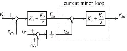
| Fig. 4 shows a block diagram of the averaging control. It forces the u-phase average voltage ¯vCu to follow its command v*C, where ¯vCu is given by |
 |
| Let a dc-loop current command of iZu be i*Zu, as shown in Fig. 4. It is given by |
 |
| The voltage command obtained from the averaging control, v*Au is given by |
 |
| active power should be taken from the dc power supply into the four chopper-cells. When iP u is positive, the product of vBju (= v*Bju) and iP u forms the positive active power. When iP u is negative, the polarity of vBju should get inverse to take the positive active power. Finally, v*Bju for j = 1− 4 is represented as, |
 |
| While v*Bju for j = 5− 8 is also represented as, |
 |
| Fig. 5 shows a voltage command of each chopper-cell v*ju. The positive-arm and negative-arm commands are obtained. |
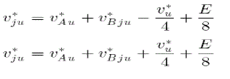 |
| where v*u is an ac-voltage command for the u-phase load. Note that Fig. 5 includes the feed forward control of the dc supply voltage E. The voltage command v*ju is normalized by each dc-capacitor voltage vCju, followed by comparison with a triangular waveform having a maximal value of unity and a minimal value of zero with a carrier frequency of fC. The actual switching frequency of each chopper-cell, fS is equal to fC. The eight chopper-cells have the eight triangular waveforms with the same frequency but a phase difference of 45âÃâæ (= 360âÃâæ/8) to each other for achieving harmonic cancellation and enhancing current controllability. |
B. Simulated Results
|
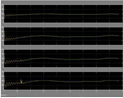
| Fig. 6 shows simulated waveforms from Fig. 1. Tables I and II summarize circuit parameters and control gains used for simulation using a software package of the “PSCAD/EMTDC” [24]. The dc supply voltage E and the rated active power P are set as E = 9 kV and P = 1 MW, and therefore, the nominal rated line-to-line rms voltage of the MMC is 5.5 kV. An intrinsic one-sampling delay occurs due to digital control. The dc capacitor voltage command of each choppercell is v*C =2.25 kV while three-phase load voltage commands of each phase are given as |
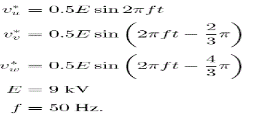 |
| Note that v*u, v*v, and v*w are the three-phase line-to-neutral voltages. In Fig. 6, each chopper cell is operated at unity modulation index. In Table I, a unit capacitance constant H is defined as, |
 |
| where VC is the rated dc voltage of each chopper cell. Note that H is defined as a ratio of all electrostatic energy stored in dc capacitors with respect to rated active power [25]. Therefore, H has a unit of second.2 Fig. 6 indicates that vuv is a 17-level line-to-line voltage, achieving voltage balancing of all the dc capacitors. The dc input power pd is represented as |
 |
| where id is a dc input current. The waveform of pd includes the following two frequency components: one is a 6thfrequency (300 Hz) component stemming from a three-phase full-bridge converter, and the other is a fundamental frequency (50 Hz) component stemming from an output frequency of 50 Hz. The detailed analysis of each waveform will be carried out in the next section. |
CONCLUSION
|
| This paper has dealt with the balancing of Multi Carrier PWM-MMCs, proposing their control method and verifying their operating principle. Computer simulation using the “PSCAD/EMTDC” software package has confirmed the proper operation of the three-phase Multi Carrier PWM-MMC. The MMC is showing considerable promise as a power converter for medium-voltage motor-drives, high-voltage direct current (HVDC) systems, STATCOMs, and back-to-back systems. Thus the output voltages are balanced even though unbalanced load is connected to the three phase system. |
Tables at a glance
|
 |
 |
| Table 1 |
Table 2 |
|
Figures at a glance
|
 |
 |
 |
| Figure 1 |
Figure 2 |
Figure 3 |
 |
 |
 |
| Figure 4 |
Figure 5 |
Figure 6 |
|
References
|
- S. Mori, K. Matsuno, T. Hasegawa, S. Ohnishi, M. Takeda, M. Seto, S. Murakami, and F. Ishiguro, “Developmentof a large static var generator using self-commutated inverters for improving power system stability,” IEEE Trans.Power Syst., vol. 8, no. 1, pp. 371–377, Feb. 1993.
- K. Kunomura, K. Yoshida, K. Ito, N. Nagayama, M. Otsuki, T. Ishizuka, F. Aoyama, and T. Yoshino, “Electronicfrequency converter,” in Proc. IEEJ IPEC, 2005, pp. 2187–2191.
- T.Uzuka, S. Ikedo, and K.Ueda, “A static voltage fluctuation compensator for ac electric railway,” in Conf. Rec.IEEE PESC, 2005, pp. 1869–1873.
- T. Fujii, S. Funahashi, N. Morishima, M. Azuma, H. Teramoto, N. Iio, H.Yonezawa,D. Takayama, and Y. Shinki,“A±80MV AGCT STATCOM for the Kanzaki substation,” in Proc. IEEJ IPEC, 2005, pp. 1299–1306.
- M. Hagiwara, P. V. Pham, and H. Akagi, “Calculation of dc magnetic flux deviation in the converter-transformer ofa self-commutated BTB system during single-line-to-ground faults,” IEEE Trans. Power Electron., vol. 23, no. 2, pp.698–706, Mar. 2008.
- F. Z. Peng, “A generalized multilevel inverter topology with self voltage balancing,” IEEE Trans. Ind. Appl., vol.37, no. 2, pp. 611–618, Mar./Apr. 2001.
- J. Rodriguez, J. S. Lai, and F. Z. Peng, “Multilevel inverters: A survey of topologies, controls, and applications,”IEEE Trans. Ind. Electron., vol. 49, no. 4, pp. 724–738, Aug. 2002.
- T. A. Meynard and H. Foch, “Multi-level choppers for high voltage applications,” Proc. EPE, Mar. 1992, vol. 2, no.1, pp. 41–50.
- Nabae, I. Takahashi, and H. Akagi, “A new neutral-point-clamped PWM inverter,” IEEE Trans. Ind. Appl., vol.IA-17, no. 5, pp. 518–523, Sep./Oct. 1981.
- H. Akagi, “Large static converters for industry and utility applications,” Proc. IEEE, vol. 89, no. 6, pp. 976–983,Jun. 2001.
- H. Akagi, H. Fujita, S. Yonetani, and Y. Kondo, “A 6.6-kV transformer less STATCOM based on a five-leveldiode clamped PWM converter: System design and experimentation of a 200-V 10-kVA laboratory model,” IEEETrans. Ind. Appl., vol. 44, no. 2, pp. 672–680, Mar./Apr. 2008.
- T. A. Meynard, H. Foch, P. Thomas, J. Courault, R. Jakob, and M. Nahrstaedt, “Multi cell converters: Basicconcepts and industry applications,” IEEE Trans. Ind. Electron., vol. 49, no. 5, pp. 955–964, Oct. 2002.
- J. Rodriguez, S. Bernet, B. Wu, J. O. Pontt, and S. Kouro, “Multilevel voltage-source-converter topologies forindustrial medium-voltage drives,” IEEE Trans. Ind. Electron., vol. 54, no. 6, pp. 2930–2945, Dec. 2007.
- R. Marquardt and A. Lesnicar, “A new modular voltage source inverter topology,” in Conf. Rec. EPE, 2003, CDROM.
- M. Glinka and R. Marquardt, “A new single-phase ac/ac-multilevel converter for traction vehicles operates on acline voltage,” in Proc. EPE, 2003, CD-ROM.
- M. Glinka, “Prototype of multiphase modular-multilevel-converter with 2 MW power rating and 17-level-outputvoltage,”in Conf. Rec. IEEE PESC, 2004, pp. 2572–2576.
- M. Glinka and R. Marquardt, “A new ac/ac multilevel converter family,” IEEE Trans. Ind. Electron., vol. 52, no.3, pp. 662–669, Jun. 2005.
- B. Gemmell, J. Dorn, D. Retzmann, and D. Soerangr, “Prospects of multilevel VSC technologies for powertransmission,” in Conf. Rec. IEEETDCE, 2008, pp. 1–16.
- S. Allebrod, R. Hamerski, and R. Marquardt, “New transformer less, scalable modular multilevel converters forHVDC-transmission,” in Conf. Rec. IEEE PESC, 2008, pp. 174–179.
- H. Akagi, S. Inoue, and T. Yoshii, “Control and performance of a transformer less cascade PWM STATCOM withstar configuration,” IEEE Trans. Ind. Appl., vol. 43, no. 4, pp. 1041–1049, Jul./Aug. 2007.
- L. Maharjan, S. Inoue, and H. Akagi, “A transformer less energy storage system based on a cascade multilevelPWM converter with star configuration,” IEEE Trans. Ind. Appl., vol. 44, no. 5, pp. 1621–1630, Sep./Oct. 2008.
- L. Maharjan, S. Inoue, H. Akagi, and J. Asakura, “A transformer less battery energy storage system based on amultilevel cascade PWM converter,” in Conf. Rec. IEEE PESC, 2008, pp. 4798–4804.
- [Online]. Available: http://www.hvdc.ca/
- H. Fujita, S. Tominaga, and H. Akagi, “Analysis and design of a dc voltage controlled static varcompensatorusing quad-series voltage-source inverters,” IEEE Trans. Ind. Appl., vol. 32, no. 4, pp. 970–977, Jul./Aug. 1996.
|