Keywords
|
| BLDC motor, four quadrants, regenerative braking. |
INTRODUCTION
|
| The Brushless DC (BLDC) motor with the advantages of small size, high power density and easy control of operation, has been widely used in the areas of aviation, automobile electronics and household appliances [1]. Motor has a rotor with permanent magnets and a stator with windings. It is essentially a DC motor turned inside out. The brushes and commutator have been eliminated in BLDC motor and the windings are connected to the control circuits. The function of the commutator is replaced by control circuits which energizes the proper winding. The motor has less inertia, therefore easier to start and stop. BLDC motors are potentially faster, efficient, noiseless and reliable. The Brushless DC motor is driven by rectangular or trapezoidal voltage strokes coupled with the given rotor position. The voltage strokes must be properly aligned between the phases, so that the angle between the stator flux and the rotor flux is kept close to 90áõÃâ to get the maximum developed torque. BLDC motors use either internal or external position sensors to sense the actual rotor position or its position can also be detected without sensors. |
FOUR QUADRANT OPERATION
|
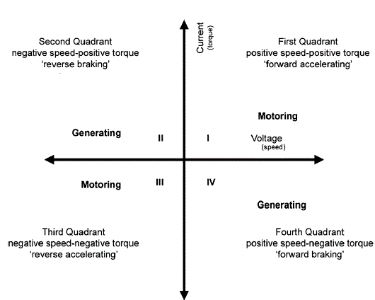
| There are four possible modes or quadrants of operation using a Brushless DC Motor which is depicted in Figure 1. When BLDC motor is operating in the first and third quadrant, the supplied voltage is greater than the back emf which is forward motoring and reverse motoring modes respectively, but the direction of current flow differs. When the motor operates in the second and fourth quadrant the value of the back emf generated by the motor should be greater than the supplied voltage which are the forward braking and reverse braking modes of operation respectively, here again the direction of current flow is reversed. The BLDC motor is initially made to rotate in clockwise direction, but when the speed reversal command is obtained, the control goes into the clockwise regeneration mode, which brings the rotor to the standstill position. Instead of waiting for the absolute standstill position, continuous energization of the main phase is attempted. This rapidly slows down the rotor to a standstill position. Therefore, there is the necessity for determining the instant when the rotor of the machine is ideally positioned for reversal. |
PROPOSED SCHEME
|
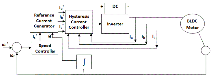
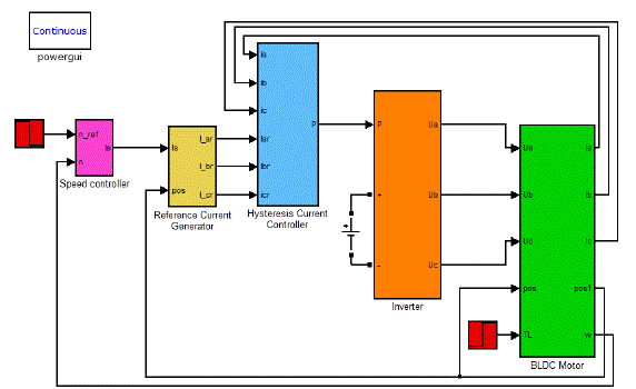
| Figure 2 describes the basic building blocks of the PMBLDCM drive. The drive consists of speed controller, reference current generator, PWM current controller, position sensor, the motor and IGBT based current controlled voltage source inverter (CC-VSI). |
| A. Modelling of BLDC Motor |
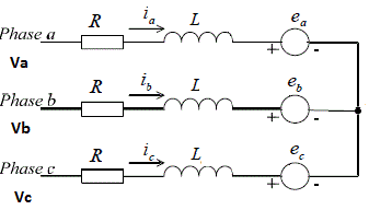
| The equivalent circuit of a Y-connection BLDC motor [3]-[5] |
| A BLDC motor has three stator windings and permanent magnets on the rotor. Its voltage equation of three windings with phase variables is: |
 |
| where Va , Vb ,Vc are the phase voltages, ia , ib ,ic are the phase currents, Ea, Eb, Ec are the phase back- EMF, R is the phase resistance, L is the self inductance of each phase. |
| And the electromagnetic torque equation is |
 |
| where ωm is the speed of the rotor and Te is the electromagnetic torque. The equation of motion is: |
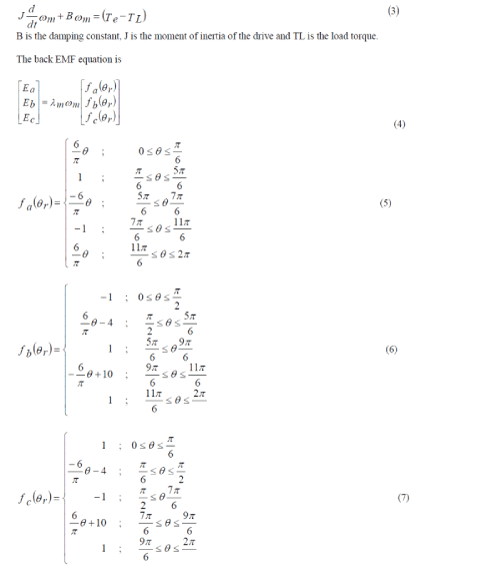 |
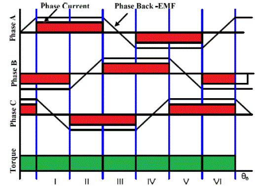
| where λm is the flux linkage, θr is the rotor position in radian and the functions fa(θr), fb(θr), fc(θr) have the same shape as Ea, Eb, Ec with a maximum magnitude of ±1.The induced emfs do not have sharp corners because these are in trapezoidal nature. |
B. PI CONTROLLER
|
| A proportional integral-derivative is the control loop feedback mechanism used. PI controller attempts to correct the error between a measured process variable and desired set point by calculating and then outputting corrective action that can adjust the process accordingly. The PI controller calculation involves two separate modes the proportional mode, integral mode. The proportional mode determine the reaction to the current error, integral mode determines the reaction based recent error. The weighted sum of the two modes output as corrective action to the control element. The speed of the motor is compared with its reference value and the speed error is processed in proportional- integral (PI) controller. The output of this controller is considered as the reference torque. A limit is put on the speed controller output depending on permissible maximum winding currents. |
C. THE REFERENCE CURRENT GENERATOR
|
| The magnitude of the three phase current I*is determined by using reference torque reference T* |
 |
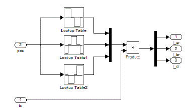
| where KT is the torque constant. Depending on the rotor position, the reference current generator block generates threephase reference currents Ia*, Ib*, Ic* by taking the value of PI speed controller and limiter. The reference currents are fed to the PWM current controller. The reference current for each phase are function of the rotor position. |
| Table 1 and Table 2 lists the relationship of angle θ and the current of the three-phase winding. |
| D. HYSTERESIS CURRENT CONTROLLER |
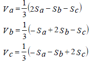
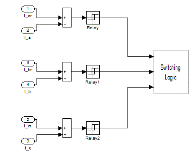
| The Hysteresis current controller contributes to the generation of the switching signals for the inverter. Hysteresis-band PWM is basically an instantaneous feedback current control method of PWM where the actual current continually tracks the command current within hysteresis-band. As current exceed upper band limit the upper switch is off and lower switch is on. As the current exceed lower band limit upper switch is on and lower switch is off like this control of the other phase going on. According to above switching condition of the inverter output voltage are given below |
 |
E. VOLTAGE SOURCE INVERTER
|
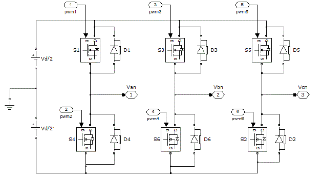
| The inverter supplies the input voltage for the three phases of the BLDC motor. The inverter is implemented using equations (7) |
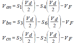 |
| where Van , Vbn and Vcn are line-neutral voltages |
| Vd is the DC-link voltage. |
| VF is the forward diode voltage drop. |
SIMULATION RESULTS
|
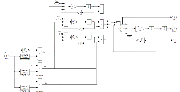
| Simulation of the drive model with is done in MATLAB/ SIMULINK. Runge-Kutta numerical integration method is used to get the solution of the equations. The responses of a 3 phase, 4 pole, 2000 rpm, 2.0 h.p PMBLDC motor are shown in Figures. The specifications of the PMBLDC motor are given in Table 3. |
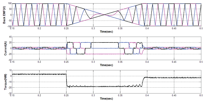
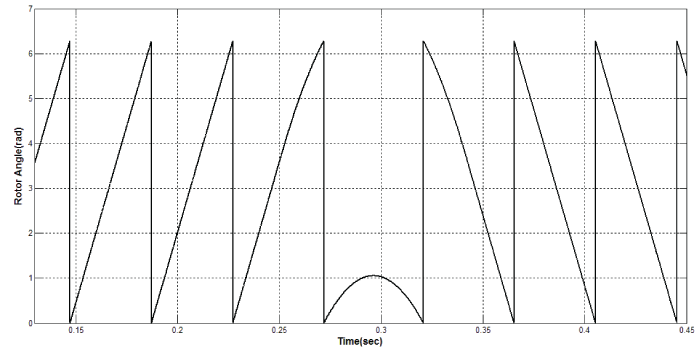
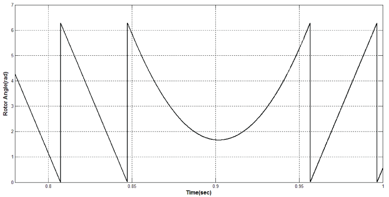
| The motor is operated in four steady state operating modes of torque-speed plane. At first, the motor is operated in Forward motoring mode, when a speed reversal command is given, the motor undergoes braking operation in forward direction, with speed tending to zero and starts rotating in reverse direction. Variation in speed, phase currents, three phase back emf and torque is as in Figure 11. The variation of rotor position when the motor is changing from forward braking mode to reverse motoring mode is shown in Figure 12. When a speed reversal command is issued again, the motor undergoes reverse braking and operates in Forward Motoring mode. In other words, motor rotates in forward direction. The rotor position varies as shown Figure 13. |
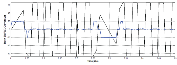
| In the motoring mode, the back-emf magnitude increases until the steady state is reached and in braking mode backemf starts decreasing towards zero. The Figure 14 shows the changeover of back–emf from braking mode to motoring mode. In the motoring mode, the corresponding back-emf and phase current is in phase. In braking mode the back- EMF and phase current are out of phase as shown in the Figure 14. |
| The back EMF in the brushless DC motor (BLDC) is directly proportional to the speed of the rotor and field strength of the motor, which means that if the speed of the motor or field strength is increased, the back EMF will be increased and if the speed of the motor or field strength is decreased, the back EMF is decreased. The back EMF created acts as a resistance, and resistance in a line reduces and opposes the current flow so if the speed of the motor or field strength is increases, the back EMF increases which in turn increases the resistance to the current flow in windings and hence only less current is delivered to the motor. Also if the speed of motor or field strength decreases, the back EMF decreases, which in turn reduces the resistance and hence more current flow to the motor |
CONCLUSION
|
| The modelling procedure presented in this paper helps in simulation of BLDC drive system for four quadrant operation. The performance evaluation results show that, such a modelling is very useful in studying the drive system before taking up the dedicated controller design, accounting the relevant dynamic parameters of the motor. |
Tables at a glance
|
|
|
Figures at a glance
|
 |
 |
 |
 |
 |
| Figure 1 |
Figure 1a |
Figure 2 |
Figure 3 |
Figure 5 |
 |
 |
 |
 |
 |
| Figure 6 |
Figure 7 |
Figure 8 |
Figure 9 |
Figure 10 |
 |
 |
 |
 |
| Figure 11 |
Figure 12 |
Figure 13 |
Figure 14 |
|
References
|
- T. J. E Miller, Brushless Permanent Magnet and Reluctance Motor Drives, Clarendon Press, Oxford, 1989.
- R. C. Becerra, T. M. Jahns, and M. Ehsani, "Four-quadrant sensorless brushless ECM drive," in Proc. IEEE Appl. Power. Electron. Conf.,APEC’91, pp. 202-209, 1991.
- P.Pillay and R.Krishnan, “Modeling, simulation and analysis of Permanent-magnet motor drives, part-II: the brushless DC motor drives,”IEEE Trans. on Industry Applications, vol. 25, pp.274- 279, March/April1989.
- P. Yedamale, Microchip Technology Inc., “Brushless DC (BLDC) motor fundamentals,” 2003, AN885.
- B. Singh and S. Singh, “State of the art on permanent magnet brushless DC motor drives,” J. Power Electron., vol. 9, no. 1, pp. 1–17, Jan.2009.
- C. S. Joice and Dr. S. R. Paranjothi, “Simulation of closed loop control of four quadrant operation in three phase brushless DC motor usingMATLAB/simulink,” in Proc. ICPCES, 2010, pp. 259–263.
- “Simulation of four quadrant operation & speed control of BLDC motor on MATLAB/SIMULINK,” in Proc. IEEE Region 10 Conference,2008, pp. 1–6.
- C. S. Joice and Dr. S R Paranojothi, “Digital control strategy for four quadrant operation of three phase BLDC Motor with Load variations;”IEEE Trans. Industrial Informatics, vol. 9, n0. 2, May 2013.
|