The perception of this paper based on a project done for adjusting and monitoring of fuel supply in power plant boilers using LabVIEW. For power generation, in thermal power plant system water is converted to steam and the steam is send it to the high pressure turbine in order to rotate the shaft then the power has been produced. The Natural Gas (Methane, CH4) is used as more reliable fuel for boilingthe water. The fuel supply is controlled by using Programmable Logical Controller (PLC) mechanism. The proposed method has implemented using LabVIEW for monitoring and controlling the fuel supply for increasing the fuel efficiency and safety. Fuel Supply System (FSS) has modeled in LabVIEW for easy access of the system. The communication between the LabVIEW and PLC is done by using Object Linking and Embedding for Process Control (OPC) server software. This proposed method the natural gas is controlled and energize, two boilers and one pilot's gun is used for ignition.
Keywords |
| LabVIEW, PLC, Power Plant, OPC Server, Boiler. |
INTRODUCTION |
| Most of the power generation system in the thermal power plant, steam is used to rotate a turbine and power has been
generated. Steam is generated by boiling water. To boil water, Natural gas (Methane, CH4) is used [11]. In this boiler,
the water is heated with the steam temperature (520 0C) and it is transmitted through heat resistive pipes to the turbine.
It causes of auxiliary equipment to burn it is expensive, so a separate ignition control Liquefied Petroleum Gas (LPG) is
used. The natural gas has various advantages such as auxiliary cost for igniting the fuel is low.Themonitoring and
controlling is done using PLC with LabVIEW Environment. The programmable logical controller SLC 500 series 5/04
is used. And the interfacing with LabVIEW is achieved through an OPC serversoftware enabling.The Boiler is filled
with natural gas. Steam from the boiler’s passes through a flow meter and then to the turbine. Suitable taps are provided
with pipesit determines the quality by measuring the pressure and temperature. A main valve is used to control the flow
rate of the boiler. The output shaft of the turbine is coupled to the alternator. A panel mounted tachometer is provided
to measure the turbine speed. |
| Primarily a control signal is sent from the controller to check the residual air stuck up in the line, for that the vent
valves were turned ON. It also makes sure there is no any previous air stuck inside. Then the main Natural gas line
starts, the receiving pressure is 10kg/cm2. A pressure gauge and a pressure transmitter are used for monitoring and
control of the Fuel Supply system. By using a mass flow meter the flow is measured, and the pressure is adjusted to
5kg/cm2, by using control and diaphragm valve. |
| Another part goes to a series of pressure switch, which connected to the controller and the pressure maintains to
1kg/cm2. It goes to the two boilers. This fuel meets up with ignite, which already been lighted and fired up the boiler.
The status of the flame is monitored using a film scanner and controlled using a solenoid valve. One boiler consists of
two drums, where the lowered drum is heated and the steam goes to the top one, where, the residual condensed water
held in the second drum is sent back this process is continues it also called as a cyclic process. Thus the water is
converted to steam by using Natural gas as a fuel and the turbines are rotated to produce energy.Automatic/Semiautomatic
Control schemessaves the operational costs and operational time. Therefore, minimizing operating costs and
improving efficiency are key objectives of the operation and maintenance of power plant.The test ring consists of a
steam turbine coupled to an alternator both mounted on a suitable base plate. |
RELATED WORK |
| Automation of laboratory based mini Thermal Power Plant &Virtual simulation is achieved by automatic controllers
and the simulation model provides the visual idea for the mini Thermal Power Plant [1]. SCADA systems are used to
monitor and control a plant in industries such as waste control, energy, oil and gas refining and transportation [2]. The
development of SCADA system for laboratory based mini Thermal Power Plant systems using LabVIEW data logging
and supervisory control module [3]. The PLC is used as an industrial computer playing the role of a control device and
push buttons, level flow sensors provide incoming signals to the control unit. This prototype model provides the levels
for the tank systems developed by using Ladder Diagram [4]. LabVIEW based Data Acquisition and Management
Systems [5]are implemented for the configuration of remote terminal units to access and transmit real time data over
the intranet [6]. |
FUNCTIONALBLOCK DIAGRAM OF FUEL MONITORING SYSTEM |
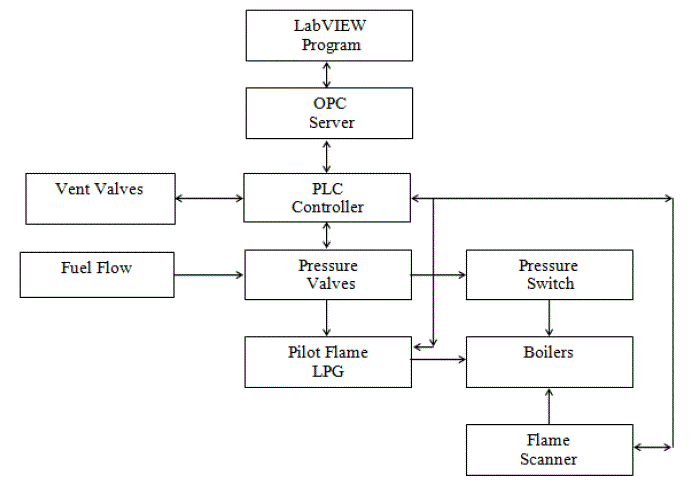
| Functional Block Diagram of Fuel Monitoring System is shown in Fig. 1. In this FMS the PLC is used as the main
controlling part of the system where the LabVIEW program with OPC server helps to monitor and control the system
for easy and reliable operations[7]. The Boilers, Valves, Pilot Flame, Pressure valves, Pressure switch and Flame
scanner are monitored and controlled by the LabVIEW program through the PLC. |
WATER TUBE BOILERS |
| A Water Tube Boiler (WTB) is a type of boiler in which water circulates in tubes heated externally by the fire. Fuel is
burned inside the furnace, creating hot gas, which heats water in the steam-generating tubes. In smaller boilers/Mud Drum, additional generating tubes are separate in the furnace, while larger utility boilers on the water-filled tubes that
make up the walls of the furnace to generate steam. The heated water then rises into the steam drum. Here, saturated
steam is drawn off the top of the drum. Superheated steam is a dry gas and therefore used to drive turbines, since water
droplets can severely damage turbine blades. |
PLC SLC 500 SERIES 5/04 |
| In this project we use SLC 500 series of PLC. Some of the features of SLC 500 series of PLC’s are SLC 5/02 through
SLC 5/05 controllers support Universal Remote I/O or Device Net™ I/O, using a scanner module [6], [7]. SLC BASIC
(1747-BAS) module adds BASIC/C programming capability 4096 Input and 4096 Output Ports, Battery 1747-BA. The
program scans 0.9 ms, I/O scans 0.255 ms.Communication port DH485 andRS232 for Serial Communication. |
FLAME SCANNER |
| Flame detection is the technology for detecting flames, using a Flame Detector. Flame Detectors are optical
equipment for the detection of flame phenomena of a fire.The Uvisor™ SF810 is used in this project.The Uvisor™
SF810 is an instrument designed to detect and analyse flames easily and reliably. It takes advantage of the latest
technologies available to make flame detection and analysis as a cost-efficient as possible. |
GAS IGNITOR/PILOT FLAME |
| A pilot light is a small gas flame, usually natural gas or liquefied petroleum gas, which is kept alight in order to serve
as an ignition source for a more powerful gas burner.MaxFire Gas Igniter is provided with Forney’s HESI spark source.
The HESI produces a powerful 12-joule spark approximately three times per second at the primary combustion zone. |
MASS FLOW METER |
| A mass flow meter, also known as an Inertial Flow Meter is a device that measures mass flow rate of a fluid
traveling through a tube. Micro Motion Coriolis meters are used here these are the leading precision flow and density
measurement solutions for the measurement of gas, and liquids. |
FRONT PANEL FOR FMS |
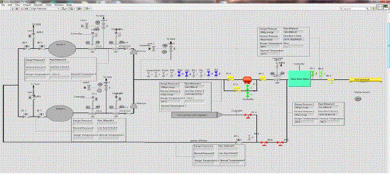
| The Fig 2 shows the front panel of the fuel status from the boiler and also from this window the technician can monitor
and control the flow of fuel [8]. These data are acquired from the PLC with the help of OPC server software. The OPC
server software will act as the communication link between PLC and LabVIEW. |
BLOCK DIAGRAM FOR FMS |
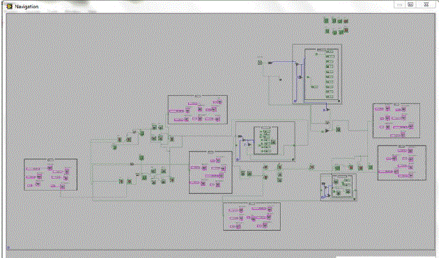
| The Fig 3 shows the Block Diagram of Fuel Monitoring Systemfor the boiler unit. These data are acquired from the
PLC with the help of OPC server software. The OPC server software will act as the communication link between PLC
and LabVIEW. The data’s from the PLC are received through variables in the OPC Server. The OPC server is to allow
direct use of the absolute PLC Variables without declaration. It is also possible to use symbolic addressing as defined in
the PLC program. These variables are accessed from LabVIEW with the Help of Data socket and Data binding in tools
in LabVIEW [10], [11]. |
RESULT AND DISCUSSION |
| xUsing the Fuel Supply Monitoring System the Fuel usage has been reduced when compared to the previous systems.
This proposed FMS in the Thermal power Plant has reduced the several security problems andit also helps to improve
the fuel conception in the power plant to 10% compared to the previous system. The Fig.2 shows the Front panel of the
FMS through which the user can easily control and monitor the system. The Block Diagram window is the back end
programming window that is shown in Fig.3 through which the program is connected to PLC through OPC server. The
flow control help to decrease the fuel usage and it help to improve the power plant efficiency. |
CONCLUSION AND FUTURE WORK |
| The proposed method, the fuel power supply of Boiler unit in the power plants are implemented by the usage of OPC
server program and communicated with LabVIEW environment to the PLC network. The smoke emission has been
controlled by using the Natural gas as a fuel. Then the test results have been verified.The interfacing of PLC through
OPC servers in the monitoring system of fuel supply in the power plant has found to be successful.Improvement will
help to increase the security and reliability of the system. Extending the program for the data logging system will
improve the reliability of the system.Design and development of alarm systemsfor automatically send notifying emails
will help to monitor and data logging remotely. |
Figures at a glance |
 |
 |
 |
| Figure 1 |
Figure 2 |
Figure 3 |
|
References |
- BinduPillai, DharaTrivedi, Vishal Mehta &Nilam Patel, “automation and virtual simulation of laboratory based mini thermal power plant”, International Journal of Mechanical and Production Engineering Research and Development, Vol. 3, Issue 4, pp.69-76, Oct 2013.
- BinduPillai, Vishal Mehta, Nilam Patel, “Development of Supervisory Control and Data Acquisition system for Laboratory Based Mini Thermal Power Plant using LabVIEW”,International Journal of Emerging Technology and Advanced Engineering, ISSN 2250-2459, Volume 2, Issue 5, May 2012)
- V.Rajeswari, Prof.Y.Rajeshwari, Dr.L.Padma Suresh, “Real- Time Implementation of Hydroelectric Power Plant Using PLC and SCADA”, International Journal of Engineering Research and Applications
- Prof. Mr. C. S. Patil Mr. H. M. Sonawane, K. G. Patil, ”Overview of SCADA Application in Thermal Power Plant”, international journal of advanced electronics & communication systems, ICMSET,february, 2014.
- K. Krishnaswamy, M. Ponnibala, “Power Plant Instrumentation”, PHI Learning Private Limited, pp. 28-33,182-196
- Nader N. Barsoum, Pin Rui Chin, “Ethernet Control AC Motor via PLC Using LabVIEW”, Intelligent Control and Automation,2011, 2, 330- 339, http://www.SciRP.org/journal/ica
- Basil Hamed, “Implementation of Fully Automated Electricity for large Building Using SCADA Tool like LabVIEW”, Current Trends in Technology and Sciences, Volume:1, Issue:1, July-2012.
- Baily D, Wright E, Practical SCADA for Industry, Elsevier journal of process plants, may 2003.
- M. N. Lakhoua, SCADA applications in thermal power plants, International Journal of the Physical Sciences Vol. 5(6), pp. 1175- 1182, June 2010.
- Jeffrey Travis, Jim Kring, “LabVIEW for Everyone: Graphical Programming Made Easy and Fun”, Prentice Hall, 2006.
- Fuel Flexibility White Paper GE Energy /Addressing gas turbine fuel flexibility/GER4601(05/11)revB.
|