Keywords
|
| Internal model control (IMC), load frequency control (LFC), model-order reduction (MOR), robustness. |
| NOMENCLATURE OF POWER SYSTEM PARAMETERS |
| ΔPd Load disturbance (p.u.MW). |
| KP Electric system gain. |
| TP Electric system time constant (s). |
| TT Turbine time constant (s). |
| TG Governor time constant (s). |
| R Speed regulation due to governor action (Hz/p.u.MW). |
| Δf(t) Incremental frequency deviation (Hz). |
| ΔPG t Incremental change generator in output (p.u MW) |
| . ΔXG Incrmental change in governor valve position. |
INTRODUCTION
|
| Imbalances between load and generation must be within seconds to avoid frequency deviations that might threaten the stability and security of the power system. The problem of controlling the frequency in large power systems by adjusting the production of generating units in response to changes in the load is called load frequency control (LFC). The Objectives of LFC are to provide zero steady-state errors of frequency and tie-line exchange variations, high damping of frequency oscillations and decreasing overshoot of the disturbance so that the system is not to farfrom the stability.Many control strategies like Fuzzy logic PI and PID controllers[7] &[9], optimal control[3], Variable structure control[5], adaptive and self-tuning control[6] ,discrete time sliding mode control [8], , and robust control [10] , [11] etchave been reported in the literature as an existing LFC solution. It is observed in power systems that the parameter values in the various power generating units like governors, turbines, generators, etc., fluctuate depending on system and power flow conditions which change almost every minute. Therefore, parameter uncertainty is an important issue for the choice of control technique. Hence, a robust strategy for LFC is required which takes care of both the uncertainties in system parameters and disturbance rejection. |
| In this paper the same method of IMC controller design via model order reduction(MOR) as in [2] is adapted to twoarea and four area power system having identical areas with non-reheat turbines and compared with different controller configurations and the system is subjected to different load changes i.e. different cases of load changes in single area, and a case of load change in different areas.Initially the system frequency deviations are zero before any disturbance, a step load change is applied to a single area in first case and system behavior is observed without any controller,after then the proposed controller with only frequency change as input is used and the results are observed in comparison with previous ones, In all the cases it is observed that the negative overshoot is reduced monotonically, and damping of the oscillations is also increased.Hence this acceptable performance in single area power system gave an idea of extending this work to multi i.e. two and four area power system and examining its performance in multi area . |
MOTIVATION AND PROBLEM STATEMENT
|
| In order to design a robust controller for LFC problem, various control strategies as mentioned in the introduction section are useful. However, one class of strongly directional control strategy that has received extensive research in electric power components and process engineering is internal model control (IMC) [12]–[15]. This class of control technique is known to exhibit robustness, sub-optimality, less computational burden, and analytical as well as easily understandable approach. However, IMC has a little edge in comparison to aforementioned techniques with reference to command following and disturbance rejection. In literature, it is reported that it is also possible to optimise system performance for load disturbance rejection without sacrificing nominal set-point tracking using two degree- of-freedom (TDF) IMC [16]–[17]. |
| As far as power system is concerned , one issue is that the inter connection of power systems result in huge increase in both the order of the system and number of controllers. With the ever-growing complexity of power systems in the electricity generation industry, formation of reduced-order models of these large-scale systems are extremely important. So in such cases, model-order reduction plays an important role in simplifying the design and implementation of the control systems. Moreover, as the size of model reduces, its computational complexity, size, and cost reduces. In [2], Saxena and Yogesh has proposed new strategy of IMC design via model order reduction(MOR) for single-area power systems, can also fulfil the control objectives in a satisfactory manner. So, this work motivated us to evaluate this IMC based controller using model-order reduction scheme for internal-model of a plant and extending it to multi area power system. Therefore, this new control strategy for LFC which is proposed which is a combination of modified IMC filter design and model-order reduction designed controller is capable of handling plant/model mismatches and parameter uncertainties. |
| More specifically, we aim to accomplish the following research objectives:- |
| a)Reduce the order of single-area power system having non- reheated type turbine. For simplicity, model-order reduction scheme of Padé [18] and Routh approximations [19] are applied. These reduced order models are treated as internal (predictive) models for imc structure |
| b)Consider TDF-IMC structure to optimize the performance of system for load disturbance rejection. The structure and proposed controller synthesis scheme is employed to demonstrate the effectiveness of utilizing reduced order models. |
| c)Evaluating it for single-area power system and extending it for two and four area power system. |
IMC THEORY AND MODEL ORDER REDUCTION
|
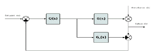
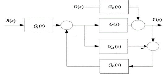
| The schematic representation of IMC structure is presented in Fig.1. The structure is characterized by a control device consisting of the feedback controller Q(S) , the real plant to be controlled G(s), and a predictive model of the plant, i.e., the internal-model GM(S). The internal-model loop uses the difference between the outputs G(s) of GM(S) .This difference commonly known as an error, represents the effect of disturbances D(s) and plant/model mismatch if exists. The two-step procedure for designing IMC controller is |
| 1) Factor the model as |
 |
| such that GM+(S) is a non-minimum phase part and GM−(S) is a minimum phase |
| 2) Define the IMC controller as |
 |
| Where F(s) is a low-pass filter, commonly of the form |
 |
| In(3),λ is a tuning parameter, which adjusts the speed of response of a closed-loop system, and also removes plant/model mismatch which generally occurs at high frequency, thus responsible for robustness, n is an integer, chosen such that Q(S) becomes proper/semi-proper for physical realization. |
Two-Degree-of-Freedom IMC Controller
|
| IMC scheme is based on pole-zero cancellation. It can achieve very good tracking ability; however, the response to disturbance rejection may be sluggish. So, a trade-off is required, where the performance for load disturbance rejection occurs by sacrificing set-point tracking. To avoid this problem, two different controllers QD(s) and Q1(s), as shown in Fig. 2, are introduced in basic IMC structure [4]. Now, the set-point response and disturbance response of the modified IMC structure namely TDF-IMC, can be improved, and each In this presented work, we have considered the TDF-IMC structure as shown in Fig. 2, and applied the design scheme recently developed by Liu and Gao [4]. In Fig. 2, we can define QD(s) as a disturbance rejection filter (feedback controller) and Q1(s) as a set-point filter. The closed-loop complementary sensitivity function T(s) and multiplicative error Ãâ ÃÂ(s) which is a measure of plant/model mismatch can be defined respectively by |
 |
| and |
 |
| Since an effective IMC filter suggested in [24] is adopted to design IMC based controller for second-order internalmodel of a system, therefore F(s), of the form (3) is replaced by a modified filter F’(s) such that |
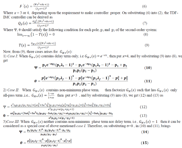 |
| Thus, it is clear that controller QD(S) expressed by (7) does not require heavy computational burden. Hence, controller’s simplicity and easy practical implementation are the major advantage of this design scheme. Here, we are only concerned with disturbance rejection problem, i.e., effect of D(S) on Y(S) we need not to evaluate set-point Q1(S)filter since R(S) = 0 is assumed. |
| B .Model Order Reduction |
| By model-order reduction we mean roughly that the large scale system (higher-order or full-order) is approximated by small-scale system (lower-order or reduced-order), such that the inherent behavior of the original system does not deteriorate.In terms of control perspective, the basic concept behind the model-order reduction technique is to preserve the dominant poles of the full-order model of the plant while rejecting the non-dominant poles. Until now, many model reduction techniques have been developed [18]–[24]. These methods can be utilized for SISO/MIMO systems to obtain lower-order models which further can be used to design IMC based controller. As an example of utilizing reduced order modeling, only two methods: Padé and Routh approximations [18], [19] are considered in the present study. The application of these techniques to LFC is elaborated in Section V. |
PROPOSED IMC STRATEGY
|
| As discussed earlier in order to apply IMC design scheme a perfect model is required. Furthermore, the controller must able to invert the model perfectly. However, in real time applications, it is difficult to get a perfect model. So, generally the process is approximated as first-order or second-order plus dead time (FOPDT or SOPDT) model. This results in addition of delay terms in the transfer function. Since the IMC controller needs inverse plant model, and the inversion of delay terms for controller design leads to predictor action .Moreover, most often the obtained transfer function is of higher-order which sometimes leads to unrealizable controller and results into slower response, and more complex computation. Thus, there is a need of model-order reduction techniques to develop causal, realizable, and lower-order processmodels. |
| So, based on Sections III, the proposed IMC design involves following two steps |
| 1)Approximate the model of a system using Padé or Routh approximation techniques. |
| 2)Evaluate the TDF-IMC controller QD(s) for this approximated (reduced) model. |
LFC FOR SINGLE-AREA POWER PLANT
|
| A)Plant Description |
| Usually, the power systems are large-scale systems with complex nonlinear dynamics [25]. However, for relatively load disturbance, they can be linearized around the operating point. Here, a single-area power system supplying power to a single service-area through single generator is considered. This power plant for LFC design consists of governor Gg s , non-reheated turbine Gt s , load and machine GP s , and 1/R is the droop characteristics, a kind of feedback gain to improve the damping properties of the power system. The linear model of plant is shown in Fig. 3. The dynamics of these subsystems are |
 |
| The whole system model can be illustrated by |
 |
| Equation (17) clearly explains that LFC is basically a disturbance rejection (regulator) problem in which the objective is to evaluate the control law :u(s)= -K(s)Δf(s) where K(s) is IMC based compensator to control the power plant G(s) and minimize effect on Δf(s) in the environment of small load disturbance ΔPD(s)[26]. |
| B. Model-Order Reduction of Plant |
| It is clear from (18) that even the single-area power system containing only one generator, still, it is of third-order, and thus IMC control design is obviously of higher order if the full-order model is used. So, we obtain the second-order reduced-model of the single-area power system using following methods. |
| 1) Padé Approximation Method : This reduction method is based on matching of few coefficients of Taylor series expansion, about s=0 of the reduced order model with the corresponding coefficients of the original model. In order to convert higher-order system G(s) into second-order reduced model GMR pade(s) , we first define GMR pade(s) as |
 |
| Equation (18) can be rewritten as |
 |
where  |
| The coefficients of the power series expansion G(s) can be expressed as G(s)= |
 |
| Now, to obtain second-order reduced model, GMR pade s of the form described in (20), the parameters ai and bi(i = 0,1) can be evaluated by simplifying |
 |
| 2) Routh Approximation Method: In this method, the reduced order model can be obtained by approximating the coefficients of Routh table.Consider a second-order reduced-model GMR routh(s) as GMR routh s = P2(s)/ Q2 (s)where P2 s and Q2 s are numerator and denominator, respectively. We first reciprocate GMR routh s using relation L~ s = 1 s L(1 s ) Thus, the reciprocated model of G~ s becomes |
 |
| and then, expand G~ s namely |
 |
| Where βi i = 1,2 are constants, Fi s (i = 1,2)and contains αi terms. Next, we need to compute α and β tables corresponding to G~ s , which is shown in Table I. The detailed study and evaluation of α and β tables are reported in [19]. These α and β terms gives reciprocated reduced-order numerator P~ 2 s and Qs ~ s denominator for second-order reduced model as |
| On substituting values of α and β in (27), we get |
  |
| Finally, the required reduced order model is obtained by again reciprocating the terms of (28), which gives |
 |
SIMULATION STUDIES
|
| Consider the typical values of parameters for single-area power system as expressed in [1]: |
 |
 |
| which is a third-order under-damped system. Since IMC requires a plant model in its control structure, so, before applying the proposed scheme as mentioned in Section IV, consider the predictive model GM(s) for IMC structure same as the original full-order power plant, i.e., GM(s)= G(s) . The various steps to provide the proposed design scheme are as follows. |
| A.Application of Model-Order Reduction |
| Using Padé approximation and Routh approximation method, the second-order reduced models of (31) are |
 |
 |
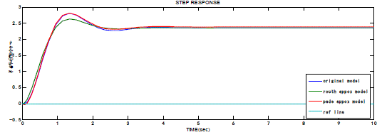
| The step responses of the original model, i.e., full-order mode G(s) and reduced order models expressed in (32) and (33), respectively, are shown in Fig. 4. From this figure, it is evident that the response of the original third-order model is almost equal to that of reduced second-order models. Thus, we can say that two models are in good approximation. |
| B. Application of Proposed Controller Design |
| 1) Controller for Padé Approximation Model: Since (32) has RHP zero at s=15.89, and therefore in order to factorize (32),) G pade Mr + (S) can be written as |
 |
| WhereG pade Mr − s is a minimum phase part: |
 |
| and G pade Mr + (S) is a non-minimum phase part: |
 |
| Taking λf =0.08, and using (12) and (13), the TDF-IMC controller of the form (7) is given by Where Ψ, θ, λf and x are 0.0057, 0.1687 and 3, respectively. |
 |
| 2) Controller for Routh Approximation Model: For evaluating TDF-IMC controller when Routh approximated reduced second-order model expressed in (33) is used, there is no need to factorize (33) because it does not contain any RHP zero or delay factor. So, in this case,G pade Mr =G pade Mr − Now, λf =0.2 selecting , and using (14) and (15), the controller is givenby |
 |
| where Ψ , θ and x are 0.1419, 0.5862, and 4, respectively. |
| Here we have applied a non-periodic load disturbance Δ PD(t)=0.01at t=2sec as shown in Fig. 3. |
| C. Performance Evaluation and Comparative Remarks |
| The effectiveness of the resulting controller is compared with the IMC tuned PID controller developed by Wen Tan [1].The disturbance rejection response of the power system for nominal case of imc tuned pid, Padé and Routh approximation models are illustrated in Fig. 6. The comparison of the three response reveals that Routh and Pade approximated model are efficient models to obtain TDF-IMC controllers and reaches frequency deviation zero faster. |
SIMULATED MODEL OF TWO AND FOUR AREA POWER SYSTEM
|
A.TWO AREA POWER SYSTEM:
|
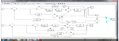
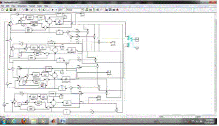
| A two area simulink model using proposed controller which is adapted in the work is shown in fig.6. Each area is assumed to have only one equivalent generator and is equipped with governor- turbine system.The terms showed in the figure are termed in the nomenclature above. |
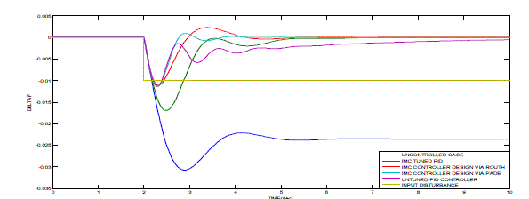
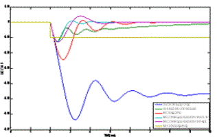
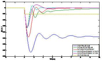
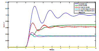
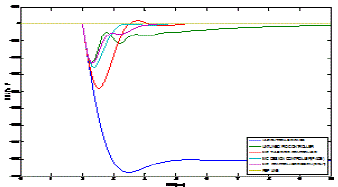
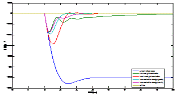
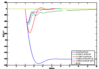
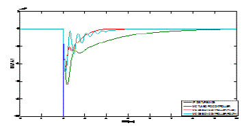
| The output responses of two area power system with non reheat turbine for varies configuration is shown below figure |
B.FOUR-AREA POWER SYSTEM
|
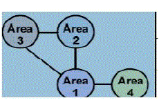
| Power systems have variable and complicated characteristics and comprise different control parts and also many of the parts are nonlinear [.These parts are connected to each other by tie lines and need controllability of frequency and power flow. Interconnected multiple-area power systems can be depicted by using circles. A simplified four area interconnected power system used in this study is shown in Fig. 1. |
ROBUSTNES AGAINST UNCERTAINITY IN MODEL PARAMETERS
|
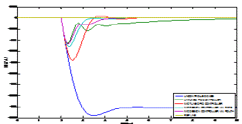
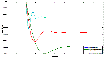
| The disturbance response of the power system without any control for nominal as well as uncertain models are shown in Fig.16, which states that the disturbance at output is approximately 50% higher for nominal case, and 100%, 150% more for +50% and -50% uncertain model, respectively, as compared to the input disturbance. In such cases, it is essential to confirm whether the same controller can handle all such parameter uncertainties .Here, we have considered 50% additive uncertainty in all the parameters. |
| Fig. 17(a) and (b) shows the disturbance rejection response for and +50% and -50% uncertain systems. Thus, it is evident that the same controllers, expressed in (37)–(38), for each model are indeed capable of handling parameter variations, and achieve superior performance compared to the controller proposed in [23]. Thus, the proposed schemes robust in nature |
CONCLUSION
|
| In electricity power industry, there is an ongoing need for efficient and effective LFC techniques to counter the everincreasing complexity of large-scale power systems As seen from the results, for the uncontrolled case which is represented in solid line has more negative overshoot and more oscillations, which are decreased by applying different proposed controllers and configurations. . A TDF-IMC controller via MOR(using routh and pade appoxiamation) is used for load frequency controller of single area power system has been presented and implemented for multi area power system .The comparative study shows that system performance characteristics of TDF-IMC via MOR method (proposed controllers) is better than IMC TUNED PID controller or unturned pid controller and is more effective in reducing the frequency deviation transients, maintain the robust performance, minimize the effect of disturbances and specified uncertainties, very effectively. |
FUTURE SCOPE
|
| Hence future scope of present work is that to investigate the efficient model order reduction techniques for achieving better appoxiamation to full order system and effective performances of the system. |
Tables at a glance
|
 |
| Table 1 |
|
Figures at a glance
|
 |
 |
 |
 |
| Figure 1 |
Figure 2 |
Figure 3 |
Figure 4 |
|
 |
 |
 |
 |
| Figure 5 |
Figure 6 |
Figure 7 |
Figure 8 |
|
 |
 |
 |
 |
| Figure 9 |
Figure 10 |
Figure 11 |
Figure 12 |
|
 |
 |
 |
 |
 |
| Figure 13 |
Figure 14 |
Figure 15 |
Figure 16 |
Figure 17 |
|
References
|
- W. Tan, “Unified tuning of PID load frequency controller for power systems via IMC,” IEEE Trans. Power Syst., vol. 25, no. 1, pp. 341–350,Feb. 2010.
- SahajSaxena, Student Member, IEEE, and Yogesh V. Hote, Member, IEEE, “ Load Frequency Control in Power Systems via Internal ModelControl Scheme and Model-Order Reduction"
- C. E. Fosha and O. I. Elgerd, “The megawatt-frequency control problem: A new approach via optimal control theory,” IEEE Trans. Power App.Syst., vol. PAS-89, no. 4, pp. 563–567,1970
- T. Liu and F.Gao, “New insight into internalmodel control filter design for load disturbance rejection,” IET Control Theory Appl., vol. 4, no.3,pp. 448–460, 2010.
- R. K. Cavin, M. C. Budge, and P. Rasmussen, “An optimal linear system approach to load frequency control,” IEEE Trans. Power App. Syst., vol.PAS-90, no. 6, pp. 2472–2482, 1971.
- M. Calovic, “Linear regulator design for a load and frequency control theory,” IEEE Trans. Power App. Syst., vol. PAS-91, no. 6, pp. 2271–2285,1972.
- M. F. Hossain, T. Takahashi, M. G. Rabbani, M. R. I. Sheikh, and M. Anower, “Fuzzy-proportional integral controller for an AGC in a singlearea power system,” in Proc. 4th Int. Conf. Electrical and Computer Engineering (ICECE), Dhaka, Bangladesh, Dec. 2006, pp. 120–123
- K. Vrdoljak, N. Peric, and I. Petrovic, “Sliding mode based load-frequency control in power systems,” Elect. Power Syst. Res., vol. 80, no. 5, pp.514–527, May 2009.
- B. VenkataPrashanth, “Robust fuzzy load frequency controller for a two area interconnected power system,” journal of theoretical and appliedinformation tech., 2005-2009, jatit.
- G. Ray, A. N. Prasad, and G. D. Prasad, “A new approach to the design of robust load-frequency controller for large scale power systems,”Elect. Power Syst. Res., vol. 51, no. 1, pp. 13–22, Jul. 1999.
- S. Taher and R. Hematti, “Robust decentralized load frequency control using multi variable QFT method in deregulated power systems,”Amer. J. Appl. Sci., vol. 5, no. 7, pp.818–828,Jul.2008.
- M. Morari and E. Zafiriou, Robust Process Control. Englewood Cliffs, NJ, USA: Prentice Hall, 1989.
- L. Harnefos and H. Nee, “Model-based current control of AC machines using the internal model control method,” IEEE Trans. Ind. Appl., vol.34, no. 1, pp. 133–141, Jan./Feb. 1998.
- M. Karimi-Ghartemani and F. Katiraei, “An adaptive internal model control for reactive power compensation,” in Proc. 2005 IEEE Conf.Control Applications, Toronto, ON, Canada, August 28–31, 2005, pp. 1668–1673.
- X. Wei, K. M. Tsang, and W. L. Chan, “DC/DC buck converter using internal model control,” Elect. Power Compon. Syst., vol. 37, no. 3, pp.320–330, Feb. 2009.
- Y. Tian and F.Gao, “Double-controller scheme for control of processes with dominant delay,” IEE Proc. Control Theory Appl., vol. 145, no. 5,pp. 479–484, 1998.
- W.Hu, G. Xiao, and W. Cai, “PID controller based on two-degree-of freedom direct synthesis,” in Proc. IEEE 2011 Control and Decision Conf.(CCDC), pp. 629–634.
- Y. Shamash, “Stable reduced-order models using Padé-type approximations,” IEEE Trans. Autom. Control, vol. 19, no. 5, pp. 615–616,Oct.1974.
- M. F. Hutton and B. Friedland, “Routh approximations for reducing order of linear, time-invariant systems,” IEEE Trans. Autom. Control, vol.AC-20, pp. 329–337, Jun. 1975.
- Y. Shamash, “Model reduction using Routh stability criterion and the Padé approximation technique,” Int. J. Control, vol. 21, no. 3, pp. 475–484, Mar. 1975.
- P. Gutman, C. F.Mannerfelt, and P.Molander, “Contribution to model reduction problem,” IEEE Trans. Autom. Control, vol. 27, no. 2, pp. 454–455, Apr. 1982.
- L. S. Shieh and M. J. Goldman, “Continued fraction expansion and inversion of the Cauer third form,” IEEE Trans. Circuits Syst., vol CAS-21,no. 3, pp. 341–345, 1974.
- C. T. Chen and C. Y. Chang, “Reduction of transfer functions by the stability-equation method,” J. Franklin Inst., vol. 308, no. 4, pp. 389–404,Oct. 1979.
- P. Kundur, Power System Stability and Control. New York, NY,USA: McGraw-Hill, 1994.
- K. Zhou and J. C. Doyle, Essentials of Robust Control. Englewood Cliffs, NJ, USA: Prentice Hall, 1998.
|