Keywords
|
| grid connected, photovoltaic (PV), pulse width modulation (PWM), proportional-integral controller, (MPPT) |
INTRODUCTION
|
| The demand for renewable energy has increased significantly over the years because of shortage of fossil fuels. Among various energy sources, solar energy and wind energy have become very popular. Solar electric energy has grown significantly by 20-25% per annum over the past 20 years. PV inverter which is the heart of the PV system is used to convert dc power obtained from PV module into ac power. |
| A typical single phase three level inverter adopts full bridge configuration by using approximate sinusoidal modulation technique as the power circuits. The output voltage then has the following three values: zero, positive(+Vdc) and negative(-Vdc)[7].The harmonic component of the output voltage are determined by the carrier frequency and switching functions. Therefore harmonic reduction is limited to a certain degree. |
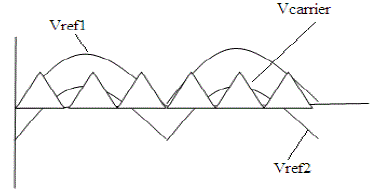
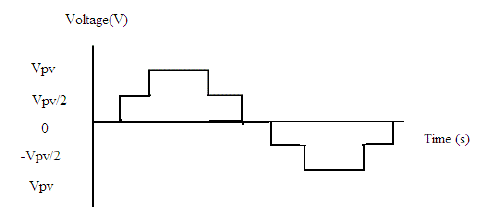
| To overcome this limitation, this paper presents a five level PWM inverter whose output voltage can be represented in the following levels: zero, +1/2 Vdc, +Vdc, -1/2 Vdcand -Vdc[2]. As the number of output voltage levels increases, the harmonic content can be reduced. This inverter topology uses two reference signals instead of one reference signal, to generate signals for the switches. Both the reference signals are identical to each other, except for an offset value equivalent to the amplitude of the carrier signal as shown in Fig. 1. |
| One of the problems in the PV generation system is the amount of the electric power generated by solar arrays always changing with weather conditions, i.e. the intensity of the solar radiation. A maximum power point tracking (MPPT) method which is able to make good use of the electric power generated in any weather conditions. |
| Because the inverter is used in a PV system, a proportional – integral (PI) current control scheme is employed to keep the output current sinusoidal and to have high dynamic performance under rapidly changing conditions and to maintain the power factor at near unity. |
FIVE-LEVEL INVERTER TOPOLOGY
|
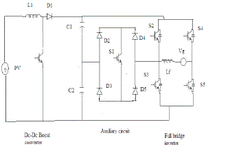
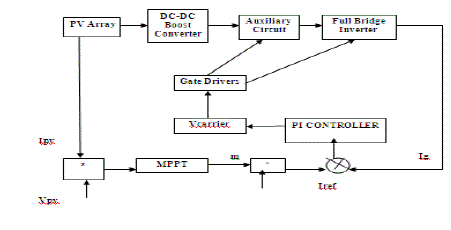
| The proposed single phase five level inverter topology is shown in Fig. 2. The inverter adopts full bridge configuration with an auxiliary circuit. PV arrays are connected to the inverter through a dc –dc boost converter. The dc –dc boost converter is used to step up inverter output voltage Vinv to be more than 2of grid voltage to ensure power flow from the PV arrays into the grid. A filtering inductance Lf is used to filter the current injected into the grid. The injected current must be sinusoidal with low harmonic distortion. The switching instant is determined from the crossing of the carrier and the modulating signal. |
OPERATING PRINCIPLE OF THE PROPOSED INVERTER
|
| Because PV arrays are used as input voltage sources, the voltage produced by the array in known as Varrays. Varraysis boosted by a dc-dc boost converter to exceed 2Vg. The proposed inverter is to generate five level output voltages, i.e. zero, +1/2 Vdc, +Vdc, -1/2 Vdc and -Vdc as in Fig. 3. Auxiliary circuit which consist of four diodes and a switch s1 is used between the dc bus capacitor and the full bridge inverter. Proper switching control of auxiliary circuit can generate half level of PV supply voltage, i.e. +1/2 Vdc and -1/2 Vdc[4]. |
| Two reference signals Vref1 and Vref2 will take turns to be compared with the carrier signal at a time. If Vref1exceeds the peak amplitude of the carrier signal Vcarrier, Vref2 will be compared with the carrier signal until it reaches zero. At this point onwards, Vref1 takes over the comparison process until it exceeds Vcarrier. This will lead to switching pattern as shown in Table 1. |
MPPT TECHNIQUE
|
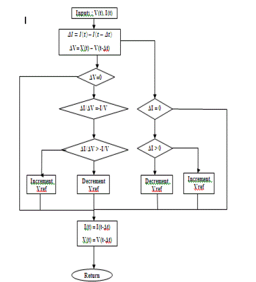
| Tracking the maximum power point(MPP) of the photovoltaic array is usually an essential part of a PV system. As such many MPP tracking (MPPT) methods have been developed and implemented. The methods vary in complexity, sensors required, convergence speed, cost etc.. Here I used incremental conductance method[11]. The incremental conductance method is based on the fact that the slope of the PV array power curve is zero at the MPP, and negative on the right, as given by |
 |
| (1) can also be written as |
 at MPP at MPP |
 left of MPP left of MPP |
 right of MPP right of MPP |
| The MPP can thus be tracked by comparing the instantaneous conductance (I/V)to the incremental conductance ΔV) as shown in the flow chart Fig. 4. Vrefis the reference voltage at which the PV array is forced to operate. At the MPP, Vrefequals to VMPP. Once the MPP is reached, the operation of the PV array is maintained at this point unless a change in ïÿýïÿýïÿýïÿý is noted, indicating a change in atmospheric conditions and the MPP. The algorithm decrements or increments the Vref to track the new MPP. |
FIVE LEVEL INVERTER WITH CONTROLL ALGOTITHM
|
| The feedback controller used in this applications utilizes the PI algorithm as shown in Fig. 5 The current injected into the grid, also known as grid current Ig, is sensed and feedback to a comparator which compares it with the reference current Iref. Iref is obtained by sensing the grid voltage and converting it to reference current and multiplying it with constant m. Constant m is derived from the MPPT algorithm. |
| The incremental conductance algorithm is used to extract maximum power from PV array and deliver it into the inverter. The instantaneous current error is fed to a PI controller. The integral term in the PI controller improves the tracking by reducing the instantaneous error between the reference and the actual current. The resulting error signal u which forms Vref1 and Vref2 is compared with a triangular carrier signal, and intersections are sought to produce PWM signals for the inverter switches. |
SIMULATION AND EXPERIMENTAL RESULTS
|
A. Modelling of PV
|
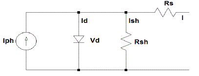
| A solar cell is the building block of a solar panel. The equivalent circuit models of PV cell is given in fig 6. The terminal equation for the current and voltage of the array becomes as follows. |
 |
| By using above equations a PV cell was simulated in matlab. Simulation results were given in fig 7. For the output characteristics the output voltage of PV is 21V and power is 37MW. |
B. Simulation Results of Inverter
|
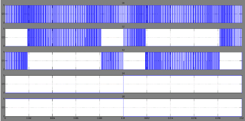
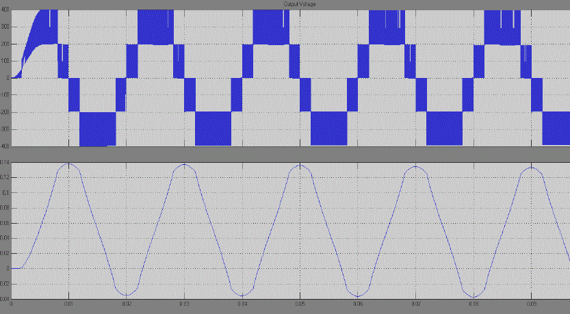
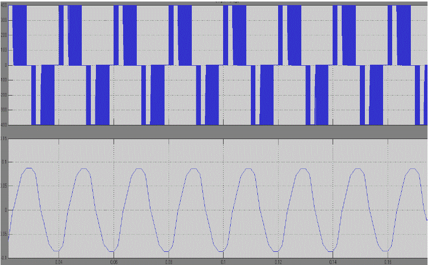
| In order to verify that the proposed inverter can be practically implemented in a PV system, simulations were performed by using MATLAB SIMULINK. Fig. 9 shows the switching status for upper and lower switches . Note that one leg of the inverter is operating at a high switching rate equivalent to the frequency of the carrier signal, whereas the other leg is operating at the rate of fundamental frequency. The output voltage and current waveforms are shown in Fig. 9. Note that we are obtained an output voltage of 400V. |
| In order to verify the improvement of the output voltage I also simulated a three level inverter. The output voltage and current wave forms are given in Fig 10.The SIMULINK MODEL of three level inverter can be obtained from five level inverter by replacing the auxiliary circuit and by modifying the switching signals. |
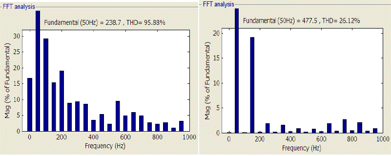
| THD of the proposed inverter and three level inverter were measured and verified. THD of three level inverter and proposed inverter were given in Fig 11. By the analysis it is clear that THD can be reduced to a comparatively low value in the proposed inverter. Thus we can conclude that by increasing the level of the output voltage we can reduce harmonic content thereby improving the performance of a PV array. |
C. Experimental Results
|
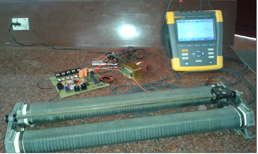
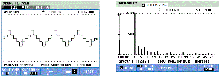
| Proposed inverter was implemented with hard ware. Fig. 12 shows the experimental setup. Output voltage and THD was measured using fluke meter and were shown in Fig. 13. |
CONCLUSION
|
| This paper presented a single phase five level for PV application. I simulated PV modele, then the proposed inverter was implemented with the pv model. The circuit topology and operation principle of the proposed inverter were analysed in derail. MPPT control algorithm with a PI controller was implemented in the control loop. Proposed inverter was compared with a three level inverter. Simulation results shows that THD level can be reduced to a low value. Proposed inverter was implemented in hardware and a five level output was obtained in a fluke meter. |
Tables at a glance
|
 |
| Table 1 |
|
Figures at a glance
|
 |
 |
 |
 |
 |
| Figure 1 |
Figure 2 |
Figure 3 |
Figure 4 |
Figure 5 |
 |
 |
 |
 |
 |
| Figure 6 |
Figure 7 |
Figure 8 |
Figure 9 |
Figure 10 |
 |
 |
 |
| Figure 11 |
Figure 12 |
Figure 13 |
|
| |
References
|
- J M Carrasco, L G Franquelo, J TBialasiewics “Power-electronic systems for the grid generation of renewable energy sources”, IEEE Trans.Ind.Electron., vol. 53, no. 4, august 2006 .
- S J Park, F S Kang, M H Lee and C U Kim, “A new single phase five-level PWM inverter employing deadbeat control scheme”, IEEE Trans.Powerelectron,vol. 18, no. 18, May 2003.
- V G Agelidis, D M Baker, W B Lawrance and C V Nayar,” A multilevel PWM inverter topology for photovoltaic applications”, IEEETrans,Portugal 1997.
- L M Tolbert and T G Habetler, “Novel multilevel inverter carrier based PWM method”, IEEE Trans, Ind,Appl, vol 35, no 15, Sep/Oct 1999.
- N C Choi, J G Cho, and G H Cho,”A general circuit topology of multilevel inverter” IEEE Trans, Jun 1991.
- A Nabae and H Akagi ,”A new neutral clamped PWM inverter”, IEEE Trans, Ind. Vol 52. Feb 2005.
- S Alepuz, S BUSquets-Monge, J Bordonau and J Balcells, “Interfacing renewable energy sources to the utility grid using a three level inverter“, IEEE Trans, Ind. Electron vol. 53, Oct 2006.
- X Kou, K Corzine and M Wielebski,”Overdistanation operation of cascaded multilevel inverters”, IEEE Trans. Ind. Appl, vol. 42 no. 3May/June 2006.
- J Rodriguez, J S Lai and F Z Peng,” Multicarrier PWM strategies for multilevel inverters”, IEEE Trans. Ind. Appl., vol.42, no. 4,Aug 2002.
- M Calais, V G Agelidis and M S Dymond,” A cascaded inverter for transformless single phase grid connected photovoltaic systems”, IEEEPESC vol. 3, 2001.
- T Esram and P L Champan, “Comparison of photovoltaic array maximum power point tracking techniques”, IEEE Trans. Ind. Electron, vol.54, no. 1. Jun 2007.
|