This paper describes a closed loop model of a current controlled PMDC motor drive with PID Controller. The output speed of the PMDC motor is compared with a preset reference speed. The differences between these two signals are fed as an error signal to the PID controller of the system. The output of the speed controller is the actuating signal that controls the duty cycle of converter and hence controls the converter output. Through this controlled converter output, required voltage gets injected into the motor to bring it back to its desired speed. As a small change in the input voltage can cause a large change in the motor current and lead to a particular drive control feature.
Keywords |
| Permanent Magnet DC motor, DC-DC Step-down Chopper, Closed Loop Control, Proportional-Integral-
Derivation controller |
INTRODUCTION |
| PM motor drives have been a topic of interest for the last twenty years. Different authors have carried out modeling
and simulation of such drives. The three most common speed control methods of a dc motor are field resistance control,
armature voltage control, and armature resistance control [6]. |
| Depending on the armature voltage control method simulink model of a current mode buck-type dc chopper-fed
permanent-magnet (PM) dc motor drive with proportional controller in its feedback loop is realized & nonlinear
dynamics and chaotic behaviour of that system is also analysed [15]. But the importance of PID controllers in process
industry cannot be overemphasized because more than half of the industrial controllers in use today utilize PID or
modified PID control schemes [8]. |
| The purpose of this paper is to investigate both numerically and through simulink model the characteristics of
different electrical parameters [current, speed, different torques working etc] of current mode buck-type dc chopper-fed
permanent-magnet (PM) dc motor with PID controller in its feedback loop. |
INTRODUCTION |
| Developments of high performance motor drives are very essential for industrial applications. A high performance
motor drive system must have good dynamic speed command tracking and load regulating response. DC motors
provide excellent control of speed for acceleration and deceleration and chopper fed permanent magnet PMDC motor
allows precise voltage control, which is necessary for speed and torque control applications. |
| DC drives, because of their simplicity, ease of application, reliability and favourable cost have long been a backbone
of industrial applications. DC drives are less complex as compared to AC drives system. DC drives are normally less
expensive for low horsepower ratings. DC motors have a long tradition of being used as adjustable speed machines and
a wide range of options have evolved for this purpose. Cooling blowers and inlet air flanges provide cooling air for a
wide speed range at constant torque. |
| PMDC motors are conveniently portable and well fit to special applications, like industrial equipments and
machineries that are not easily run from remote power sources. PMDC motor is considered a SISO (Single Input and
Single Output) system having torque/speed characteristics compatible with most mechanical loads. This makes a
PMDC motor controllable over a wide range of speeds by proper adjustment of the terminal voltage using various
innovative design and control techniques [6]. |
| In case of this project a DC-DC Step-down Chopper is used to adjust the terminal voltage as per requirement [12].
This is done by controlling switch of the chopper through a closed loop control [13]. As in process industry importance
of PID (proportional-integral-derivative) controllers cannot be overemphasized because more than half of the industrial
controllers in use today utilize PID or modified PID control schemes [9], for this reason we have also used a PID
controller in our closed control loop to generate the actuating signal which controls the chopper switch and hence
ultimately the motor speed. |
PROJECT OVERVIEW |
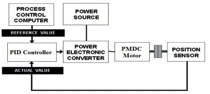
| The basic principle which has been adopted for the speed control of this modelled DC drive is variation of armature
voltage for speed below and up to rated speed with field voltage constant because of using permanent magnet dc motor
where field is produced by permanent magnets. There are two control loops, one for controlling current and another for
speed [7]. The output speed has been compared with the reference speed and error signal is fed to speed controller [8].
Now whenever a deviation of motor speed from provided reference speed occurs, controller output will vary as well.
This controller output signal termed as speed control signal [Vɷ] will control the voltage fed to the motor by
controlling the duty cycle of the convert (step down chopper) [13]. As a result, required amount of input voltage [Vin]
will be injected to the motor which will bring it back to the desired speed[4][5]. |
| A simple block diagram representation of my proposed design is shown below: |
| In case of a practical situation, output speed of motor can be measured by a position sensor [may be a Tachogenerator]. |
MODELLING OF OUR DC DRIVE SYSTEM |
| According to our discussion till now the best way to design a dc drive with speed control option is by using a DCDC
step down converter to feed the PMDC motor. Speed control will be achieved by controlling the duty cycle of the
power electronics device [GTO] used as switch. For regulation of the duty cycle, the control or error signal can be
produced by comparing the motor output speed with the reference speed and this generated error signal is fed to PID
[speed] controller. Controller output will vary whenever there is a difference in the reference speed and the actual
motor speed. The output of the PID [speed] controller or the actuating signal so generated will control the duty cycle of
converter. Now the converter output will give the required Vin required to bring motor back to the desired speed [14]. |
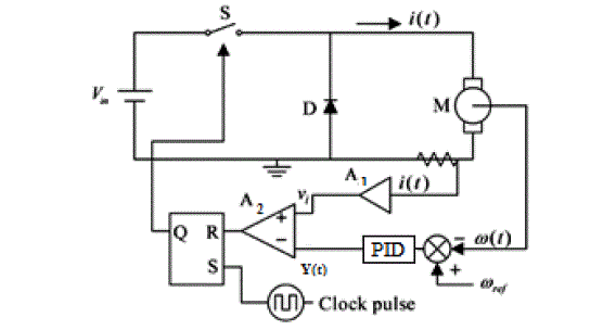
| Schematic diagram of this kind of drive is shown here: |
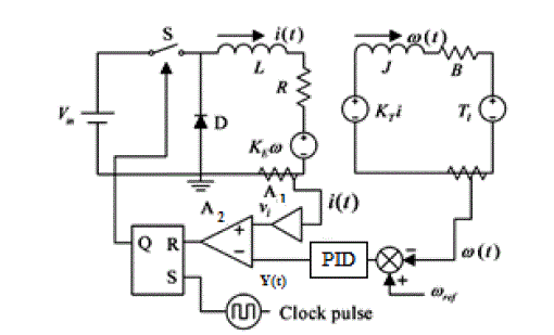
| The corresponding equivalent circuit is shown in Fig. 3 which will be used throughout the analysis: |
| Let us assume that operational amplifier A1, have gains gi , the current control signal Vi and speed control signal [in
our case output of the PID controller] y(t) can be expressed as: |
 |
 |
| Here, |
| i(t)= armature current of the dc motor, ω(t) = speed of the dc motor, ωref = reference speed of the dc motor. |
| From Fig. 3 it can be see that both y(t) and Vi(t) are inserted into the comparator A2 and this comparator outputs the
pulse to the reset of an R-S latch. This R-S latch controls the switch S of the dc-dc step down converter and a clock
pulses of period T sets the R-S latch. Once the clock pulse sets the latch, switch S is “ON” and the diode is “OFF”.
From this instance the switch S will be in “ON” until y(t) exceeds Vi(t) and at that point of time the latch will begins to
reset. After this reset S is turned off and D is on. Here on S remains open until the arrival of the next clock pulse where
it will be closed again. If both set and reset signals occur at the same time, the reset will dominate the set so that S
keeps open until the occurrence of another clock pulse. Therefore, the system equation can be divided into two stages
as given by [15] - |
| STATE EQUIATION IS GIVEN BELOW: |
| A. STAGE 1: |
| When VW > Vi means switch “S” is in ON state |
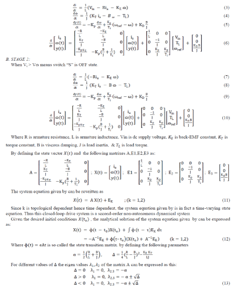 |
| Hence the corresponding state transition matrix can be obtained as for given below: |
 |
| Where I is the identity matrix and β = −Δ, for the system to be locally stable, the roots of the characteristic
equation should be in the left half plane. |
MATLAB SIMULATION RESULTS |
| As discussed up to this point, our last objective is to model and simulate [1] a buck chopper fed PMDC motor with a
PID controller oriented feedback loop through MATLAB software [2][3]. This objective is fulfilled with following
parameter values: |
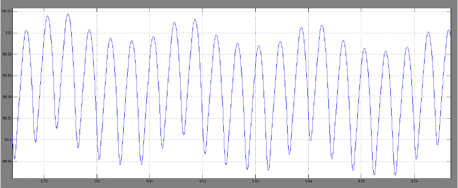
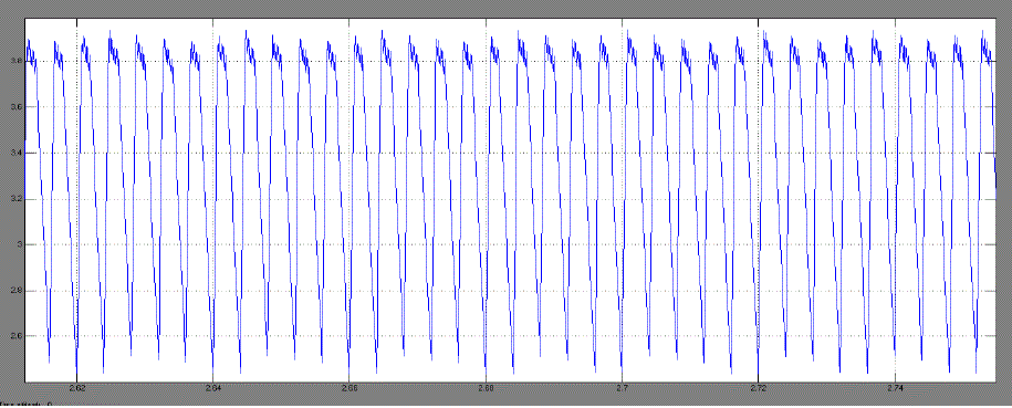
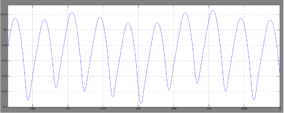
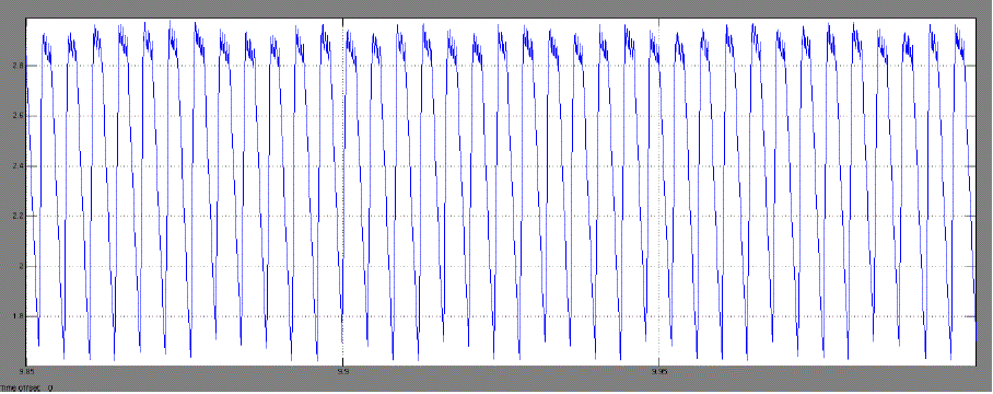
| Time Plot of speed & armature current with different load torques: |
| a. Case 1. For Tl = 0.39Nm and wref =100 |
| b. Case 2. For Tl = 0.27Nm and Wref = 100r.p.m |
| c. Phase Portrait |
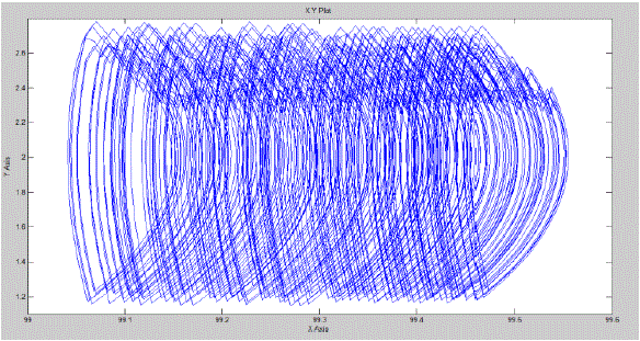
| From these results it can be seen that for different values of load torque [Tl]our designed DC drive operating with a
PMDC motor that reaches to its steady state operating condition and maintaining the speed at given reference speed.
This is happening because at steady state, load torque becoming equal to steady state torque of the motor. From Fig.8 it
can also be said that some chaotic behaviour is present in our system [10][11]. |
CONCLUSION |
| After designing the whole dc drive using MATLAB, the model has been simulated with a pre set reference speed of
100rpm and with variable load torque. It is seen that although the load torque is changed motor reached at steady state
operation with the given reference speed which is 100rmp. This means that at steady state the load torque is getting
equal to steady state torque. From this it can be concluded that the speed of the PMDC motor can be controlled
preciously as required with our proposed model. |
| At last observing from phase portrait of armature current versus speed it can be said that some chaotic behaviour is
present in this designed system. From simple understanding of the system it can be assumed that our switching circuit
for the chopper switch control may have brought these chaotic behaviour to this system. |
Tables at a glance |
 |
| Table 1 |
|
Figures at a glance |
 |
 |
 |
 |
| Figure 1 |
Figure 2 |
Figure 3 |
Figure 4 |
 |
 |
 |
 |
| Figure 5 |
Figure 6 |
Figure 7 |
Figure 8 |
|
References |
- SIMULINK, Model-based and system-based design, using Simulink, MathWorks Inc., Natick, MA, 2000..
- SimPowerSystems for use with Simulink, user’s guide, MathWorks Inc., Natick, MA, 2002.
- M. H. Nehrir, F. Fatehi, and V. Gerez, Computer modelling for enhancing instruction of electric machi-nery, IEEE Trans Educ 38 (1995).
- J. Figueroa, C. Brocart, J. Cros, and P. Viarouge,“Simplified simulation methods for polyphase brushless DC motors,” Mathematics andComputers in Simulation, vol. 63, issues 3-5, pp. 209-224, Nov. 2003.
- J. Santana, J. L. Naredo, F. Sandoval, I. Grout, and O. J. Argueta, “Simulation and construction of a speed control for a DC series motor,” Mechatronics, vol. 12, issues 9-10, pp. 1145-1156, Nov.-Dec. 2002.
- S. J. Chapman, Electric machinery fundamentals, 3rd ed., WCB/McGraw-Hill, New York, 1998.
- J. J. D’Azzo and C. H. Houpis, Linear control system analysis and design, McGraw-Hill, New York, 1995.
- K. Ogata (2009) “Modern Control Engineering, 4th Edition”, Dorling Kindersley Pvt. Ltd., India.
- K. J. Astrom and T. Hagglund (1995) “PID Controllers: Theory, Design, and Tuning”, Instrument Society of America, USA, pp. 134-151.
- D.C. Hamill and D.J. Jefferies, “Sub harmonics and chaos in a controlled switched-mode powe converter”, IEEE Transactions on Circuits and System ,vol ,35 august 1988.
- J.H.B. Deane and D.C. Hamill, “Instability, sub harmonics, and chaos in power electronic systems”, IEEE Transactions on Power Electronics, vol. 5, July 1990.
- D.C. Hamill, J.H.B. Dean, and D.J. Jefferies, CG Modeling of chaotic DC-DC converters by iterated nonlinear mappings”, IEEE Transactions on Power Electronics, vol.7, pp.25-36, January 1992.
- E. Fossas and G. Olivar, “Study of chaos in the buckconverter”, IEEE Transactions on Circuits and Systems-I:Fundamental Theory andApplications, Vol. 43, January.
- C. C. Chan and K. T. Chau, “Spectral modeling of switched-mode power converters,” IEEE Trans. Ind. Electron., vol. 41, pp. 441–450, Aug. 1994.
- K. T. Chau, J. H. Chen, and C. C. Chan, “Modeling of sub harmonics and chaos in DC motor drives,” in Proc Int. Conf. IndustrialElectronics,Control, and Instrumentation, pp. 523–528, 1997.
|