In this paper, initially, a novel secondary modulation technique is also proposed to clamp the voltage across the primary-side switches naturally with zero-current commutation. It, therefore, eliminates the necessity for an external active-clamped circuit or passive snubbers to absorb the switch turn-off voltage spike, a major challenge in current-fed converters. Zero-current switching of primary-side devices and zero-voltage switching of secondary-side devices are achieved, which significantly reduce switching losses. An interleaved design is adopted over a single cell to increase the power handling capacity obtaining merits of lower input current ripple, reduction of passive components’ size, reduced device voltage and current ratings, reduced conduction losses due to current sharing, and better thermal distribution. The multilevel inverter is simulated using MATLAB/ SIMULINK software for fifteen levels of step voltages with different DC sources Index Terms—Fuel Cell, Interleaved boost converter, Carrier Based PWM.
Keywords |
| Fuel Cell, Interleaved boost converter,
Carrier Based PWM. |
INTRODUCTION |
| TRANSPORTATION electrification has become a clear
tendency owing to lower emission, better vehicle
performance, and higher fuel economy than conventional
internal combustion (IC) engine-based vehicles. Over the
past decades, Electric vehicles, hybrid electric vehicles,
plug-in hybrid electric vehicles, and fuel-cell vehicles
(FCVs) are emerging means of transportation to replace the
conventional IC vehicle by using a three-phase electric
motor for propulsion. With the merits of cleanliness (zeroemission),
satisfied driving range, short refueling time, high
efficiency, high reliability, FCVs exhibit significant
potential in transportation. Several major automotive industries are manufacturing and testing their FCV. The
fuel-cell stack converts hydrogen gas stored onboard after
reaction with oxygen from air, i.e., oxidization, into
electricity to drive the electric motor. As long as continuity
of fuel supply is maintained, the electric motor can propel
the vehicle quietly, smoothly, and efficiently requiring less
maintenance. However, FCVs suffer from slow dynamic
response to load variation due to their slow internal
electrochemical, mechanical, and thermal dynamic
characteristics and, therefore, needs energy storage that can
deliver quick power. An auxiliary energy storage system
(ESS) such as battery or super capacitor is usually utilized
for cold start up, absorbing the regenerative braking energy,
and achieving good performance during transient operation.
High power bi-directional dc/dc converters are needed for
applications such as battery charged dischargers,
uninterruptible power systems (UPSs), alternative energy
systems, and hybrid electric vehicles. The fledgling nature
of many of these application fields may be the main
contributing factor for that only limited results are available
on this aspect so far. Most of the existing high power bidirectional
dc/dc converters fall into the generic circuit
topology illustrated in, which is characterized by a currentfed
high-frequency (HF) inverter/rectifier on one side,
preferably the lower voltage side, of the HF isolation
transformer Tr, and a voltage-fed HF rectifier inverter sub
topology on the other side. Each of these sub topologies can
be a full bridge, a half-bridge or a push-pull circuit, or their
variations. The current-fed half-bridge circuit is sometimes
also referred as L-type boost circuit, or current-doublers. |
FUEL CELL OPERATION` |
| A fuel cell is basically fed with hydrogen fuel and air at the
anode and cathode, respectively. A low voltage DC is
produced at the output, which is applied to an electric machine by processing it through a suitable power
electronic DC/DC or DC/AC converter. Basically, the
electrical machine output is a mechanical output used to
drive the wheels of the vehicle. There are 3 major steps
involved in the generation of power from a fuel cell. The
first step is to achieve purity of the available hydrogen gas.
This is done with the help of a fuel processor. A suitable
hydrocarbon fuel is fed to the fuel processor, which, in turn,
produces a hydrogen rich gas at its output. This hydrogen
rich gas is then fed to the anode electrode of the fuel cell.
The generation of the DC voltage via the fuel cell makes up
the second stage of the power processing unit. Lastly, the
power output needs to be properly treated and this is done
by passing it through an appropriate power conditioner.
Ideally, the power conditioner must have minimal losses
leading to a higher efficiency. Power conditioning
efficiencies can typically be higher than 80%. As forced to
renewable energy systems with various sources becomes
greater than before, there is a supreme need for integrated
power converters that are capable of interfacing,
concurrently, controlling several power terminals with low
cost and compact structure. Meanwhile, due to the
intermittent nature of renewable sources, a battery backup
is normally required when the ac mains is not available. |
| Fuel cells convert the chemical energy of directly into
electric energy by an electrochemical process. Low voltage
dc power is produced by using hydrogen or natural gas as
fuel. It may be defined as an electrochemical device for the
continuous conversion of the portion of the free energy
change in a chemical reaction to energy conversion. It is
distinguished from a batter in that it operates with
continuous replacement of the fuel and oxidant at active
electrode area and does not require recharging. |
| Fuel cell is one pattern of energy converter, which
converts chemical energy to electrical energy. As far as
PEMFC concerned, it converts oxygen and hydrogen
directly into electricity, heat and water in an
electrochemical process. |
| Fuel cells use electro-chemical reactions, rather than
combustion (burning a fuel) to produce electricity. The
process is the reverse of electrolysis. In electrolysis the
action of an electric current decomposes water into
hydrogen and oxygen, whereas in a simple fuel cell the two
gases can be combined electrochemically to produce
electricity, heat and water. In practice, the process is more
involved, and each type of fuel cell has its characteristics,
operating temperature, materials, and flows. What they
have in common are high electrical efficiency, no
combustion in the basic reactions, and a clean exhaust
stream. |
| Fueling The Stationary Fuel Cell A fuel cell needs H2
for fuel and some fuel cells such as molten carbonate
(MCFC) and solid oxide (SOFC) can also utilize carbon
monoxide (CO). Hydrogen may either be directly supplied
to the fuel cell or produced from other fuel sources such as
natural gas, methanol, propane, bio fuels or non-carbon
compounds. A fuel processor or electrolyze (see diagram
below) may be used to supply onsite hydrogen to the fuel
cell. |
WORKING OF THE PROJECT |
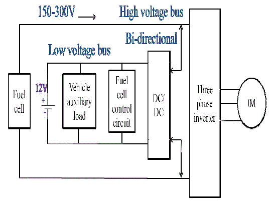
| The typical architecture of a fuel cell car is
illustrated the fuel-cell stack converts hydrogen gas stored
onboard after reaction with oxygen from air, i.e.,
oxidization, into electricity to drive the electric motor. As
long as continuity of fuel supply is maintained, the electric
motor can propel the vehicle quietly, smoothly, and
efficiently requiring less maintenance. However, FCVs
suffer from slow dynamic response to load variation due to
their slow internal electrochemical, mechanical, and
thermal dynamic characteristics and, therefore, needs
energy storage that can deliver quick power. An auxiliary
energy storage system (ESS) such as battery or super
capacitor is usually utilized for cold start up, absorbing the
regenerative braking energy, and achieving good
performance during transient operation. As illustrated by a
functional diagram of a typical fuel-cell powered
propulsion system in Fig. a fuel cell is connected to a highvoltage
dc bus acting as the main source of power. A
bidirectional dc/dc converter is utilized to interface the auxiliary power source ESS to high-voltage dc bus. This
dc/dc converter plays a vital role in coordination with the
main power source and auxiliary power source, which
needs to satisfy the following requirements: |
| 1) A high step-up ratio to boost low terminal voltage of
batteries to variable high-voltage fuel-cell dc bus (150– 300
V); |
| 2) Bidirectional power flow. The converter should be able
to supply energy during the cold startup and transition
operation in the forward direction and absorb energy during
regenerative
Braking in the reverse direction; |
| 3) High power handling power capacity; |
| 4) High-frequency (HF) operation to obtain a compact,
lightweight, high power density, and low cost system; |
| 5) High efficiency. It is a general requirement to obtain an
efficient utilization of energy and a reduced thermal design. |
| Several bidirectional dc/dc converters for FCV have been
proposed in the literature Voltage-fed converters suffer
from several limitations, i.e., high pulsating current at input,
limited soft-switching range, rectifier diode ringing, duty
cycle loss [20], and comparatively low efficiency for high
voltage amplification and high input current applications.
Compared with voltage-fed converters, current-fed
converters have been justified and demonstrated as a
suitable option for such applications. One of the very
popular topologies is a current-fed dual active bridge
converter with a HF transformer. However, the major
drawback with such a converter is high voltage spike at
device turn-off owing to the energy stored in the leakage inductance. An RCD snubber circuit was employed to limit
voltage overshoot. |
| A similar approach was applied in with a lossless snubber
circuit to reduce the voltage stress of switches. In, an active
clamping snubber circuit is used, which consists of an
active switch and a capacitor, to clamp the device voltage
and achieve ZV ZCS at the same time. However, the
disadvantages such as high current stress, higher circulating
current at light load, and related thermal issues exist. In this
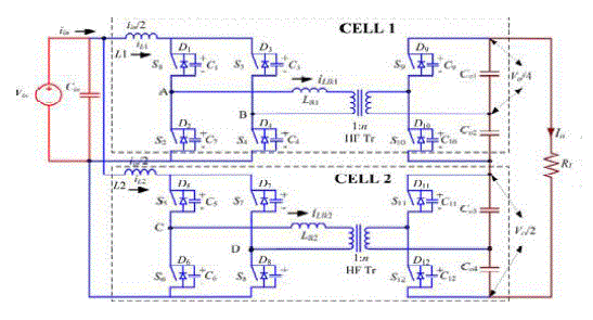
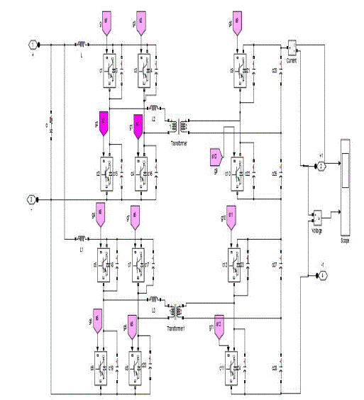
paper, novel secondary modulation-based interleaved softswitching
bidirectional snubberless current-fed full-bridge
voltage doublers is proposed, as shown in Fig. 3. The
proposed converter consists of two interleaved cells with a
current-fed full-bridge switches connected in parallel on the
low-voltage side and half-bridge voltage doublers
connected in series on the high-voltage side. For this
application, interleaved approaches (multicell) are adopted
over a single cell to increase the power handling capacity
while achieving high efficiency and reduced thermal
requirements. A voltage doublers or half-bridge is selected
to reduce the number of switches, the transformer turns
ratio, and voltage ratings of secondary-side devices. |
DC/DC INTERLEAVED CURRENT FED
FULL BRIDGE INVERTER |
| In this section, a steady-state operation and analysis with
the ZCS concept has been explained. Before turning-off of
a diagonal switch pair (S1–S4, S2–S3, S5–S8, or S6–S7) at the
primary side, the other pair of the primary-side switches is
turned ON. The reflected output voltage VO /4n appears
across the transformer primary. It diverts the current from one switch pair to the other pair causing current through
one switch pair to rise and the other pair’s current to fall to
zero. Later, the body diodes across the switch pair start
conducting and their gating signals are removed leading to
ZCS turn-off of devices. Then, the device voltage rises and
is clamped at reflected output voltage. For the simplicity of
the study of operation and analysis, the following
assumptions are made for the operation and analysis of the
converter: |
| 1) Boost inductors L1 and L2 are large enough to
maintain constant current through them. Output capacitors
Co1, Co2, Co3, and Co4 are large enough to maintain constant
voltage across them; |
| 2) All components are assumed ideal; |
| 3) Series inductors Llk1 and Llk2 include the leakage
inductances of the HF transformers; |
| 4) Magnetizing inductances of the transformers are
infinitely large. The steady-state operating waveforms are
shown in Fig. The primary switches pairs S1–S4 and S2–S3
in Cell 1 are operated with identical gating signals phase
shifted with each other by 180◦ and the duty cycle should be
kept more than 50%. The same for the switches pairs S5–S8
and S6–S7 in Cell-2. The phase difference between gating
signals of switches pairs S1–S4 and S5–S8 is 90◦. The
operation of the converter during different intervals in a
one-quarter cycle is explained with the help of equivalent
circuits shown in Fig.. For the rest of the HF cycle, the
intervals are repeated in the same sequence with other
symmetrical devices conducting to complete the full HF
cycle. |
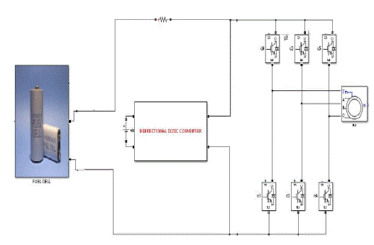
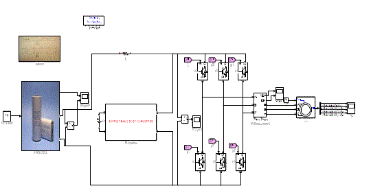
| SIMULATION OF THE FUEL CELL BASED BIDIRECTIONAL
DC/DC CONVERTER As shown in fig
6 an open- loop simulation of the proposed model is
performed using MAT lab simulink. pulse width
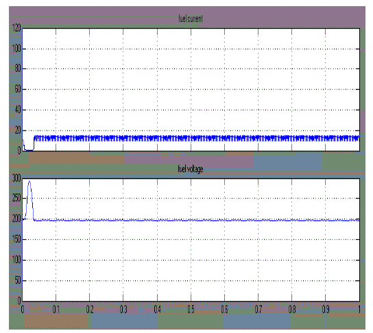
modulation is used to reduce the harmonics and improve the efficiency. The simulation results are shown in fig 7a.
The input dc voltage from the fuel cell and the AC and DC
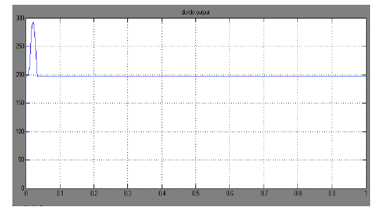
load voltages are shown in fig 7b. respectively. The output
voltage is boosted as compared with the input DC, with the
help of the interleaved boost configuration. |
SIMULATION OF FUEL CELL BASED
INTERLEAVED BOOST CONVERTER |
BI DIRECTIONAL DC/DC CONVERTER |
FUEL CELL OUTPUT VOLTAGE |
BI DIRECTIONAL DC/DC CONVERTER OUTPUT VOLTAGE |
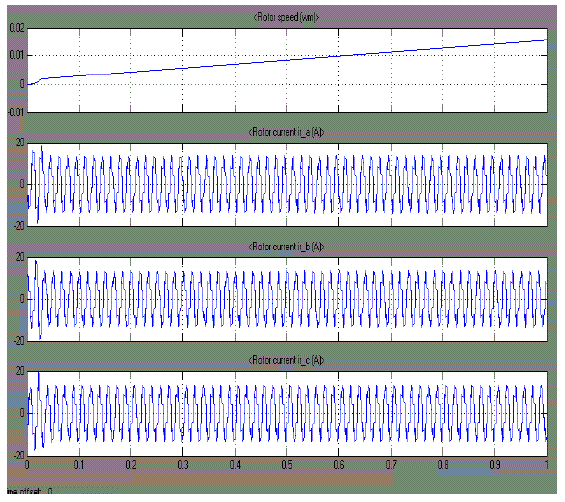
THREE PHASE INDUCTION MOTOR OUTPUT RESULTS |
CONCULSION |
| The proposed converter maintains ZCS turn-off of
primary devices and ZVS turn-on of secondary devices
throughout the wide variation of output power. Turn-on loss
of primary devices is also shown to be low. Hence,
maintaining soft-switching of all devices substantially
reduces the switching loss and allows higher switching
frequency operation of the converter to achieve a more
compact and higher power density system. The proposed
modulation technique clamps the voltage across the
primary-side devices naturally with zero-current
commutation and therefore eliminates the necessity for
active clamp or passive snubbers required to absorb device
turn-off voltage spike in conventional current-fed
topologies. An interleaved design is adopted to increase the
power handling capacity. Lower input current ripple,
reduction of passive components’ size, reduced device
voltage and current ratings, better thermal distribution are
obtained. Usage of low-voltage devices and current sharing
between interleaved cells results in low conduction losses in
primary devices, which is significant due to higher currents
on the primary side. Detailed steady-state operation,
analysis, and design have been illustrated. Simulation and
experimental results clearly confirm and demonstrate the
claimed soft-switching of all semiconductor devices, natural clamping, and zero-current commutation of
primary-side devices. These merits make the converter
promising for FCV application, front-end dc/dc power
conversion for fuel-cell inverters and ESS. |
Figures at a glance |
 |
 |
 |
 |
 |
| Figure 1 |
Figure 2 |
Figure 3 |
Figure 4 |
Figure 5 |
 |
 |
 |
 |
| Figure 6 |
Figure 7a |
Figure 7b |
Figure 7c |
|
References |
- Emadi and S. S. Williamson, âÃâ¬ÃÅFuel cell vehicles: Opportunities and challenges,âÃâ¬Ã in Proc. IEEE Power Eng. Soc., Jun. 2004, pp. 1640âÃâ¬Ãâ 1645.
- F. Z. Peng, H. Li, G. J. Su, and J. S. Lawler, âÃâ¬ÃÅA new ZVS bidirectional dcâÃâ¬Ãâdc converter for fuel cell and battery application,âÃâ¬Ã IEEE Trans. Power Electron., vol. 19, no. 1, pp. 54âÃâ¬Ãâ65, Jan. 2004.
- S. Inoue and H. Akagi, âÃâ¬ÃÅA bi-directional DC/DC converter for an energy storage system,âÃâ¬Ã in Proc. IEEE Appl. Power Electron. Conf., Feb.âÃâ¬ÃâMar. 2007, pp. 761âÃâ¬Ãâ767.
- K. Wang, F. C. Lee, and J. Lai, âÃâ¬ÃÅOperation principles of bidirectional full-bridge DC/DC converter with unified soft switching scheme and softstarting capability,âÃâ¬Ã in Proc. IEEE Appl. Power Electron. Conf., 2000, pp. 111âÃâ¬Ãâ118.
- V. Yakushev, V. Meleshim, and S. Fraidlin, âÃâ¬ÃÅFull bridge isolated current fed converter with active-clamp,âÃâ¬Ã in Proc. IEEE Appl. Power Electron. Conf., Mar. 1999, pp. 560âÃâ¬Ãâ566.
- E. S. Park, S. J. Choi, J. M. Lee, and B. H. Cho, âÃâ¬ÃÅA soft-switching activeclamp scheme for isolated full-bridge boost converter,âÃâ¬Ã in Proc. IEEE Appl. Power Electron. Conf., 2004, pp. 1067âÃâ¬Ãâ1070.
- S. J. Jang, C. Y. Won, B. K. Lee, and J. Hur, âÃâ¬ÃÅFuel cell generation system with a newactive clamping current fed half-bridge converter,âÃâ¬Ã IEEE Trans.Energy Convers., vol. 22, no. 2, pp. 332âÃâ¬Ãâ340, Jun. 2007.
|