In this work, distribution system load flow analysis is formulated and tested for fundamental steady-state and harmonics power flow. For the steady-state analysis, a novel power flow formulation method for the general multiphase balanced and/or unbalanced radial distribution systems is presented. The special topology of the power distribution system has been fully exploited to facilitate obtaining a direct solution using the graph theory. Only one developed matrix used in conjunction with simple standard formulation is enough to obtain the power flow solution. This matrix is the branch-path incident matrix. A feature of using this method is that it significantly reduces the number of power flow equations, as compared to conventional methods, hence very low computation time and memory storage. The presence of nonlinear loads in the power system causes the circulation of harmonics currents in the system, leading to harmonics voltage drops. The harmonics flow analysis in this paper, uses the network techniques in conjunction with graph theory resulting in a powerful algorithm for nonlinear load flow analysis. Six pulse converters model were used to represent the nonlinear load. Two MATLAB programs have been built and used to solve for the load flow solution of standard test systems in both steady-state and harmonics cases. The results of the distribution system cases studies are presented and shows a very good resemblance with a standard results.
Keywords |
| Distribution Networks, Novel Power flow, harmonic flow analysis, MATLAB. |
INTRODUCTION |
| The analysis of power distribution systems is animportant area of research activities due to the vitalrole of distribution
systems as the final link between thebulk power system and consumers. Load flow is animportant tool for the analysis
of distribution systems. Thistool must be able to model the special features ofdistribution systems such as unbalanced
loads;un-transposed lines, radial and weakly meshed topology,grounded or ungrounded systems, high resistance
toreactance(R/X) ratios, and single, two or three phase lines.Due to the high R/X ratios and unbalanced operation
indistribution systems, the Newton-Raphson and ordinaryFast Decoupled Load Flow method may provide
inaccurateresults and may not be converged. Therefore, conventionalload flow methods cannot be directly applied to
distributionsystems.However, these algorithms have been formulated for transmission systems. In many cases, the
radial distribution systems include un-transposed lines which are unbalanced because of single phase, two phase and
three phase loads. Thus, load flow analysis of balanced radial distribution systems [1], [2] will be in efficient to solve
the unbalanced cases and the distribution systems need to be analyzed on a three phase basis instead of single phase
basis.Conventional ac electric power systems are designed to operate with sinusoidal voltages and currents. However,
nonlinear loads cause distortion in the steady-state ac voltage and current waveforms. Periodic steady-state distortion
can be very effectively studied by examining the components of a Fourier series representation of the waveforms. A
harmonic analysis (harmonic study) is numerical tool applied to study the generation and propagation of harmonics in
an arbitrary topology network [3]. The level of power system harmonic voltages and currents has increased
significantly and there has been a considerable interest in limiting harmonic signals by adopting standards which require analytical methods to calculate harmonics in power systems. The harmonic power flow calculations are
becoming routine in many power utilities. They are being used regularly in predicting the degree of harmonic
penetration in existing systems and in the design of new systems. The accuracy of the results obtained depends to a
large extent on the accuracy of the mathematical models used for the various components and that of the simulation
technique employed [4, 5].The objective of this work is to provide a novel power flow formulation method for the
general multi-phase balanced and/or unbalanced radial distribution system. In the formulation, the special topology of
distribution system is to be exploited, to reduce the number of power flow equations, and reduce the computation time
and storage, as compared to conventional methods. In the present work a computer program in (MATLAB) is to be
developed and applied to standard test systems then a comparison with the results of existing methods in the context of
simplicity, accuracy, execution time, adaptability are to be evaluated. Finally, it is aimed to apply the developed
method to analyse harmonics load flow in radial distribution systems. |
| There have been a lot of interests in the area of three phase distribution load flows. A fast decoupled power flow
method has been proposed in [6]. This method orders the laterals instead of buses into layers, thus reducing the
problem size to the number of laterals. Using of lateral variables instead of node variables makes this method more
efficient for a given system topology, but it may add some difficulties if the network topology is changed regularly,
which is common in distribution systems because of switching operations. In [7], a method for solving unbalanced
radial distribution systems based on the Newton-Raphson method has been proposed. Thukarametal. [8] have proposed
a method for solving three-phase radial distribution networks. This method uses the forward and backward propagation
to calculate branch currents and node voltages. A three-phase fast decoupled power flow method has been proposed in
[9]. This method uses traditional Newton-Raphson algorithm in a rectangular coordinate system. In [10], a method for
the solution of unbalanced three-phase power systems using the Newton-Raphson have been proposed in which, threephase
current injection equations are written in rectangular coordinates system. However, these methods are very
cumbersome and need large computational time. A fast decoupled G-matrix method for power flow, based on
equivalent current injections, and has been proposed in [11] .This method uses a constant Jacobian matrix
which needs to be inverted only once. However, the Jacobian matrix is formed by omitting the reactance of
the distribution lines with the assumption that R>>X; and fails if X>R. |
UNBALANCED THREE-PHASE MODEL |
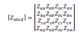
| Figure (1) shows a three-phase line section model between bus i and j. the line parameters can be obtained using the
method developed by Carson [12]. A 4×4 matrix, which takes into account the self and mutual coupling terms, can be
expressed as |
 |
| For a well-grounded distribution system, VN and Vn shown in fig.(1) are assumed to be zero, and Kron’s reduction can
be applied in (1). |
| Equation (2) is obtained after the elimination and therefore includes the effect of the neutral or ground wire and to be
used in the unbalanced load flow calculation. |
 |
| The relations between the bus voltages and branch currents in fig.(1) can be expressed as: |
 |
| For any phase which fails to present, the corresponding row and column in this matrix will contain null-entries. |
FORMULATION OF THE PROBLEM |
BRANCH-PATH INCIDENT MATRIX [BPM] |
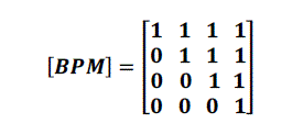
| The incidence of branches to paths in a tree is shown by the branch-path incidence matrix, where a path is oriented
from the reference node (substation in the distribution system) to a bus. The elements of this matrix are: |
| BPMij = 1 if the ith branch (B) is in the path from reference to the jth bus and is oriented in the same direction. |
| BPMij = 0 if the ith branch (B) is not in the path from reference to the jth bus. |
| With node (0) as reference the branch-path incident matrix associated with the tree shown in fig. (2) which is used as an
example given in(4). |
 |
| The building algorithm for the [BPM] is given [12]: |
| i. For a distribution system with m branch sections and n buses, the dimension of [BPM] is (m×m), (for
distribution systems the number of branches is equal to (n-1)). |
| ii.For distribution system the [BPM] branch-path incident matrix have a (+1) in all diagonal elements. |
| iii. If a branch is located between bus i and bus j, copy the column of the ith path (ith bus) of the matrix [BPM] to
the column of the jth path (jth bus). |
| iv. Repeat procedure (iii) until all the line sections (branches) is included in the branch-path incident matrix. |
THE SYSTEM MODEL |
| For distribution system, the models which are based on the equivalent current injection, as described in [13] and [14]
are used in this paper. At iteration K, the nodal current injection,Ii(k) at node( i) is calculated as, |
 |
| Where |
| Vi(k-1) is the voltage at node-i calculated during the (K − 1)ith iteration. |
| Si: Complex power injection at node-i. |
| Yi: The sum of all the shunt elements at the node i. |
| i: is integer equal (1, 2, 3,… n). |
SOLUTION TECHNIQUES & ALGORITHM |
| From graph [12] the bus impedance matrix can be found using simple relation between branch impedance (or primitive
impedance matrix) and [BPM]. The relation between branch impedance matrix and [BPM] can be expressed as: |
 |
| The relation between the bus current injections and voltage drop can be expressed as: |
 |
 |
 |
 |
| Where |
| [ZBR ]: Branch impedance matrix. |
| [ZBUS ]: Bus impedance matrix. |
| [VR]: Vector whose elements are all equal to voltage of reference-bus (Substation). |
| Therefore, the solution for the distribution load flow can be obtained by solving eqns. (5) (9) and (10) iteratively. |
| Figure (3), shows the flowchart of the overall algorithm. |
HARMONIC LOAD FLOW |
| The proposed harmonic power flow method is based on Kirchhoff laws expressed by eq. (11) in conjunction with graph
theory [15]. |
 |
| Where |
| [Zh]: is the complex nodal impedance matrix at harmonic order h. |
| [Vh]: is the complex nodal voltage vector at harmonic order h, |
| [Ih]: is the complex nodal injected current vector at harmonic order h. |
| The proposed harmonics load flow algorithm follows the steps: |
| i. Input data for load flow at power frequency. |
| ii. Calculate bus voltages and current injections. |
| iii. Input data for harmonic load flow: |
| • Maximum order of the harmonics to be considered. |
| • The negative sequence reactance of the source side. |
| • Specific data for the nonlinear loads. |
| iv. Build the bus incident matrix [A]. |
| v. Formulate the bus admittance matrix using, |
 |
| vi. Using LU-decomposition obtain the bus impedance matrix. |
 |
 |
 |
| Where |
| LU: lower & upper diagonal matrix. |
| I1: is the current amplitude at fundamental frequency absorbed for the power setting considered. |
| ∅h : is the harmonic current angular displacement. |
| h: The order of the harmonic. |
| ∝:Angle representing the delay between the moment of actual switching and that of natural switching. |
| θh :Angle equal to the phase shift between similar primary and secondary voltages on the transformer
supplying the rectifier. |
| vii. Solve equations (14) and (15) to obtain the harmonic currents generated at the nonlinear load bus for each
harmonic order. |
| viii. Solve equation (11) to obtain the bus voltage at each harmonic order. |
| ix. Add fundamental and harmonic components. |
| x. Print results and plot. |
CASE STUDIES AND RESULTS |
| The power flow algorithm's presented in section (4) and (5) above are applied to radial distribution systems. These
systems include: |
1. A RADIAL DISTRIBUTION FEEDER FROM BAGHDAD CITY NETWORK |
| This feeder is an actual feeder selected from Baghdad city network (AL-Mansoor-No.11)whose single line diagram is
shown in fig. (4). |
| The feeder nominal voltage is 11.1 kV, and connected to AL-Mansoor substation. The system relevant data are given in
table (1a & 1b) which are considered as abase values 11.1 kV and 2250 kVA [16]. All buses are loaded to 233kVA at
0.77 power factor lag except buses No-1 and No-4. |
| The graph theoretic based load flow program is used to perform the analysis for this test case under balanced three
phases loading of the feeder. The supply bus (S.S, in fig. (4)) voltage is considered (1.00) p.u. The results concerning
bus voltages, currents and branch currents are presented in tables (2) and (3). The total feeder losses are
(5.527+j5.4584) kVA. The results in Tables (2 and 3) conforms exactly those obtained by [16], which are using
thedistribution flow method. The total execution time was 0.05 Sec. |
2. THE IEEE 13 NODE TEST FEEDER |
| The single line diagram of the IEEE 13nodetestfeeder system is shown in figure (5). The relevant data for this test
system presents in [17]. |
| The results for the IEEE-13 node system for the unbalanced loading conditions are shown in Table (4).The results of
table (4) resemble those of [17] to less than 2 % as a comparison, the execution time for this case was 0.05 Sec. |
| Table (5) presents the overall power profile in the test system. Regarding system losses the resultgiven in [17] is equal
toSLoss=(45.174+j120.9582) kVA compared to (45.173+j120.957) kVA which are very close. |
3. THE IEEE 34 NODE TEST FEEDER |
| The single line diagram of the IEEE 34nodetest feeder system is shown in fig. (6). The data for this test system
presents in [17]. |
| However the sample results for the IEEE-34 nodes, multiphase unbalanced operation system are given in table (6). The
results are for samples nodes (0, 1, 2, 3, 4, and 30). Comparison of these results with those in [17] shows a very close
resemblance for the nodes given above and slight discrepancies were noticed for those nodes after the regulators in the
system. The reason for which is primarily due to the negligence of the regulator, transformers, and the concentration of
the distributed loads as a spot loads. The execution time for this system and loading was 0.16 sec compared to 0.25 sec
in [18]. |
| Only three cases above the power flow program were implemented using the MATLAB. The total number of iterations
for a solution was three - iteration with a convergence tolerance of1 × 10-3. Finally, it is worthwhile to mention that
for the IEEE-34 node system [18],theexecution time comparison for various load flow algorithms which are depicted in
Fig. (7). In addition, theexecution time for the load flow solution is obtained by using the proposed method. |
HARMONICS TEST SYSTEM |
| This is a 12.5 kV radial distribution feeder with one generator (source side), four linear loads and one nonlinear load at
bus-8 which is a six pulse rectifier. The system single line diagram is shown in Fig. (8), the system input data are given
in [19], based on 10MVA. This test is used to illustrate the application of the proposed algorithm for solving the
harmonics load flow problem in a balance radial distribution system with nonlinear load. The transformer represented
by a series reactance only. The harmonic analysis was carried out up to the 19th harmonic order, assuming the effects
from the higher order harmonics are negligible. The nonlinear load bus (bus-8) contains a six pulse converter. The
characteristic harmonic orders for this nonlinear source are (6K ±1) where K =1, 2, 3. |
| The fundamental, 5th, 7th, 11th, 13th, 17th and 19th harmonics calculated bus voltages are shown in Table (7). The
decay in the harmonics voltages away from the harmonic bus (bus-8) is quite evident in Table (7). |
| The percent voltage distortion factor at each bus is shown in figure (9). The distortion factor variation pattern and
values obtained compares very well with the results in [19]. |
| Figures (11)-(13), presents the voltage waveforms (one cycle) at selected buses, namely, buses 1, 4 and 8 respectively.
The corruption in the waveform is quite clear being the highest in the non-linear load bus (bus-8) and the least at the
farthest bus (bus-1). |
CONCLUSION |
| A novel, fast, robust load flow algorithm applicable in electrical power distribution system analysis for various loading
and phasing conditions is presented. The conformity of the results obtained for the different systems with those
reported in the literature verifies the applicability and robustness of the proposed method. Work is going on to
introduce the regulation, transformer and the distributed load nature if exists in the system, and to be reported in a
future paper. The fast, low storage and versatility of the algorithm lends it effectively to computer automation
applications in distribution systems. |
| The proposed harmonic power flow method is simple and fast based on Kirchhoff laws in conjunction with graph
theoretic procedure. It is linear methods were no iterations are required, only the harmonic currents and the bus
impedance for each harmonic order is needed. Therefore, compared to nonlinear methods, the proposed technique
offers the benefits of very low computation time and storage. The six pulse converter approximate model been used
along with the system components at the particular frequency. The overall conclusion prevailed showed that the
harmonics flow is strongly connected to the nonlinear load position and definitely on the harmonic order. |
Tables at a glance |
 |
 |
 |
 |
| Table 1a |
Table 1b |
Table 2 |
Table 3 |
|
 |
 |
 |
 |
| Table 4 |
Table 5 |
Table 6 |
Table 7 |
|
Figures at a glance |
 |
 |
 |
 |
| Figure 1 |
Figure 2 |
Figure 3 |
Figure 4 |
 |
 |
 |
 |
| Figure 5 |
Figure 6 |
Figure 7 |
Figure 8 |
 |
 |
 |
 |
| Figure 9 |
Figure 10 |
Figure 11a |
Figure 11b |
 |
 |
 |
 |
| Figure 12a |
Figure 12b |
Figure 13a |
Figure 13b |
|
References |
- D. Das, D. P. Kothari, and A. Kalam. , "Simple and efficient method forload flow solution of radial distribution systems," Electrical PowerandEnergy Systems, vol. 17, no. 5, pp. 335-346, Oct. 1995.
- P. Aravindhababu, "A new fast decoupled power flow method fordistribution systems," Electric Power Components and Systems ,vol. 31, no. 9,pp. 869-878, Sept. 2003.
- IEEE Task Force on Harmonics Modeling and Simulation, “Modelling and Simulation of the Propagation of Harmonics in Electric PowerNetworks. Part II: Sample systems and examples", IEEE Transaction on power delivery, Vol. 11, No. 1, January 1996.
- Tamby, J. P. and John, V. I, "Q' Harm-A Harmonic Power Flow Program for Small Power Systems", IEEE Transaction on power systems, Vol. 3,No. 3, August 1988.
- HEYDT, G.T, "The Present Status of Harmonic Power Flow Studies", Electric Energy Conversion in Power System-CAPRI, May, 1989.
- Ray. D Zimmerman, and Hsiao-Dong. H, “Fast decoupled power flow for unbalanced radial distribution systems," IEEE-PES Winter Meeting,paper no. 95, New York, 1995
- S. K. Goswami and S. K. Basu, "Direct solution of distribution systems," IEE Proc., pt. C, vol. 188, no. 1, pp. 78-88, 1999.
- D. Thukaram, H. M. Wijekoon Banda, and J. Jerome, "A Robust three phase power flow algorithm for radial distribution systems," ElectricPower System Research, vol. 50, no. 3, pp. 227-236, Jun. 1999.
- W. M. Lin, Y. S. Su, H. C. Chin, and J. H. Teng, "Three-Phase unbalanced distribution power flow solutions with minimum data preparation,"IEEE Trans. on Power Systems, vol. 14, no. 3, pp. 1178-1183, Aug. 1999.
- P. A. N. Garcia, J. L. R. Pereira, S. Carnerio, V. M. da Costa, and N. Martins, "Three-Phase power flow calculations using the current injectionmethod," IEEE Trans. on Power Systems ,vol. 15, no. 2, pp. 508-514, May 2000.
- W. M. Lin and J. H. Teng, "Three-Phase distribution networks fast decoupled power flow solutions," Electric Power and Energy Systems, vol.22, no. 5, pp. 375-380, Jun. 2000.
- Stagg , G. W. and A. H. EL-Abiad, Computer methods in power system analysis, McGrow-Hill Book Co.1968.
- D. Shirmohammadi, H. W. Hong, A. Semlyen, and G. X. Luo, “A Compensation-based power flow Method for weakly Meshed Distributionand Transmission Networks”, IEEE Transactions on Power System, Vol. 3, No. 2, May 1988, pp. 753-762.
- JEN-HAO TENG, “Network-Topology-based Three-Phase Load Flow for Distribution Systems”, Proc. Natl. Sci. Counc. ROC(A), Vol. 24, No.4, 2000. pp. 259-264.
- M. A. Pesonen, "Harmonics Characteristic Parameters Methods of Study, Estimates of Existing Values in the Network", Electra, July 1981, No.77, PP. 35-54.
- Mohamed R. Yousif, ''Power and energy loss Reduction in Baghdad city distribution system'' M.Sc. Thesis, university of technology Baghdad,May 2002.
- Kerstig, W. H. '' Radial distribution test feeders '' IEEE Transactions on power system Vol.63, August 1991, PP. 975-985.
- Yong-Jin Jang, '' Three-phase Power-flow Method based on Fast decoupled Method for Unbalanced Radial Distribution-System”,http://eeserver.Korea.ac.kr/~bk21/arch/bk21cont/45.pdf, 2002.
- Grady, W. M. and Heydt, G. T. "Voltage and Current Distortion in Power System Caused by Six Pulse Line Commutated Converters" Midwestpower symposium, Ames, Iowa, October 1983.
|