ISSN ONLINE(2319-8753)PRINT(2347-6710)
ISSN ONLINE(2319-8753)PRINT(2347-6710)
K Ramesan1, D.Ramegowda2
|
| Related article at Pubmed, Scholar Google |
Visit for more related articles at International Journal of Innovative Research in Science, Engineering and Technology
Our agriculture system now facing of severe productivity decline due to the increased cost of production. One of the major problem, this sector facing is non availability of enough water and power. The cost per unit power is increasing day by day so we introduce a novel technique to irrigate the plant with conserving both power and water. The traditional irrigation system supply fixed quantity of water to the field without considering the crop water requirement. The crop water requirement varies according to the weather and other environmental conditions. A dynamic head water supply system is essential to meet the crop water requirement and there by optimizing the productivity. Existing technology uses sensor based on/off controlled irrigation system with area varying technique. In this paper a novel technique of irrigation system is presented. Here the crop water demand is assessed by pan evaporation water level method. Which is a water head demand is communicated to supply water head system. The input parameters measured from pan evaporation are modeled and estimated the time for maintaining water required for irrigation. These results are then simulated. Data collected from CPCRI Kasaragod for the year 2012 of pan evaporation and field data is compared.
Keywords |
| variable head, PID Controller, Automated hardware, Irrigation scheduling, Evapotranstiration. |
INTRODUCTION |
| Ancient time itself human beings were using different irrigation methods for the cultivation. Egyptian and Indus valley civilization were very much advanced in this area. The modern society is now using many methods which are efficient also. This topic actually focusing on a new approach to the plant irrigation. Automation setup beyond mechanization which use control system to reduce human intervention is necessary. The water requirement for each crop is different and this may vary every day according to the climate conditions of that particular day [1]. Now a days we are facing very acute water shortage, moreover traditional irrigation the over watering and insufficient watering leads to poor yielding. So the input water quantity has to be precisely calculated and it should be supplied at the proper time. The input water quantity requirement is measured from the evaporation rate in the pan. [2] The evaporation rate in the evopan corresponds to the evapotranspiration rate for the particular plant. Evaporation pans provide a measurement of the integrated effect of radiation, wind, temp, humidity on evaporation from an open water surface. Evopan data can be used for irrigation scheduling, often used to estimate for water resource planning. The experimental investigation of pan evaporation. Measurements coupled with required automation for data acquisition, process, storage and electrical signals and numerical information for computing are needed. Corresponding to the input parameters, the supply rate is controlled by controlling the pressure head of the storage tank. A relay controlled water pump maintains this water level in the storage tank. The on/off time of the pump is determined by the control unit and communicated to the relay. Hence the water conservation and optimum power saving can be achieved by this method. The automation with irrigation of installations and operations of level sensor, analog digital converter interface with computer system with required software for data acquisition and analysis are done to this work. |
IRRIGATION SYSTEM |
| Irrigation systems [1] are classified according to the pressure requirement. Water pressure is required for |
| Frictional losses from bank to the distribution end of the system |
| The pressure required at the emitter and |
| The difference in elevation |
| The water flow (lit/sec) inversely proportion to the duration of application it is the time requirement of the completion of an irrigation cycle. |
| Total pressure = static pressure + dynamic pressure |
| Bernoulli derived from the principle of conservation of energy (see appendix-A) |
| 1. Variable Head or Dynamic Head |
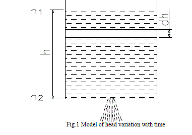
| Elevation head and frictional losses head are considered as static head. The emitter pressure or supply pressure depend up on this variable head. So variable head in the tank (h) = Volume of water in that tank/ Area of the tank. Here area of the tank is fixed and so Variable head (h) = Q/A where Q = Demand of water per day in m3/ day. |
| 2.Time required for maintaining the Dynamic head |
 |
| Let |
 |
 |
MODELING SYSTEM PARAMETERES |
 |
| 1. Input parameters |
| Pan evaporation level in which level variation should be defined as a signal [3] and plot the graph days Vs. Evaporation in mm per day. Evaporation for any day can be simulated by changing the variable |
| 2. Evotranspiration |
| It is the soil evaporation plus plant |
| Transpiration [2,4-6]. That is, |
| ET0= KEpan |
| ET0 –be the evapotranspiration in mm per day |
| K = Crop coefficient |
| Epan = pan evaporation |
| 3. Control unit |
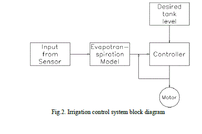
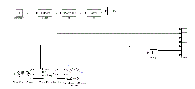
| Control unit consists of PID controller, this system controller interface the required quantity of water and measured quantity of water. The main function of this closed loop system is to keep required quantity close to the measured quantity of water. The output of this result controls the input of the motor relay and maintains the variable dynamic head of water requirement to optimize the whole system. The controller has two inputs, which is pan evaporation level and calculated required tank water head from evapotranspiration model. And there is only one output of controller is known as input for motor relay position. Fig.3 shows the PID based control system with evaporation model diagram. Lab View contains 3 components, the front panel, block diagram and connector pane. Front panel with control and indicators. Controls are input devices and indicators are graphs. Lab View to communicate with hardware such as data acquisition and motion control devices. In Fig.3 h= pan evaporation rate, Q= crop water requirement, H=tank water level and T= time for maintaining water level. |
 |
 |
 |
SIMULATION RESULTS. |
| The proposed scheme has been simulated for various input data using MATLAB assisted technology and results are plotted. The outcome of the simulation result shows that time for maintaining dynamic head of the crop water requirement varies with pan evaporation rate, which is directly related with combined effect of temperature, wind speed, humidity etc. So requirement is calculated precisely. |
| The simulation result shows tank water level variation according to the pan evaporation rate. |
| This simulation shows the evaporation rate directly effects the crop water requirement. |
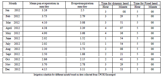
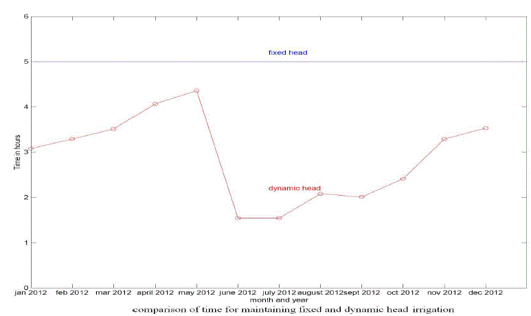
| The fixed head irrigation supply the same quantity of water throughout the year irrespective of the requirement of the plant |
| [7,8], which shows in the fig.5 |
| In dynamic head irrigation system the demand of the plant is assessed first and water supply is regulated correspondingly. |
| Simulation results show that quantity of crop water requirement by considering coefficient of crop factor. |
| Fixed head irrigation time is constant throughout the year |
| In dynamic head irrigation time varies throughout the year |
| Hence power saving also will be one of the major advantages. |
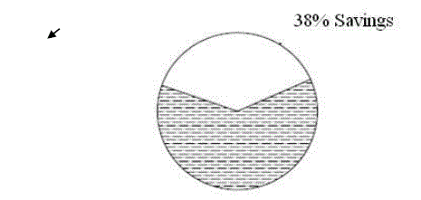
| According to CPCRI, Kasaragod data and simulation result variable rate supply shows 38% of time saving compared to fixed quantity. |
 |
CONCLUSION |
| This paper provides the day today calculation of time for maintaining dynamics head of crop water requirements. The automated irrigation system is the integration of hardware and software which gives optimum use of power and water resulting better yield. Controller module in Lab view which can be easily connected to hardware for pan evaporation real time use. |
ACKNOWLEDGEMENT |
| Our sincere thanks to meteorological department, CPCRI for providing data of pan evaporation rate during the year 2011. Authors would like to thank Ashokan from NIT Calicut, Valsan and Jayaprakash from GEC Kannur and Sreekanth from IIT Madras for useful discussions. |
APPENDIX |
| A. Conservation of Momentum, 1 dimension, steady flow |
| Let x be distance u, velocity a, acceleration t, time m, mass p- density A, Area F, force and p, pressure |
 |
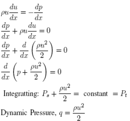
| B. Dynamic Pressure |
| From the conservation of fluid momentum, if p is the pressure, p is the density and u is the velocity we have |
 |
References |
|