The appearance of radix-2^2 was a milestone in the design of pipelined FFT hardware architectures. Later, radix-2^2 was extended to radix-2^k. However, radix-2^k was only proposed for singlepath delay feedback (SDF) architectures, but not for feed-forward ones which is also as called multi-path delay commutator (MDC). This paper presents the radix-2^k feedforward (MDC) FFT architectures. In feedforward architectures, radix-2^k can be used for any number of parallel samples which is a power of two. Furthermore, both decimation in frequency (DIF) and decimation in time (DIT) decompositions can be used. In addition to this, the designs can achieve very high throughputs, which make them suitable for the most demanding applications. Indeed, the proposed radix-2^k feed-forward architectures require fewer hardware resources than parallel feedback ones, also called multi-path delay feedback (MDF), when several samples in parallel must be processed. As a result, the proposed radix-2^k feedforward architectures not only offer an attractive solution for current applications, but also open up a new research line on feedforward structures.
INTRODUCTION |
| In the present technologies, since the throughput required is in the order of giga samples per second, there arises a
need for pipelining, parallelism and efficient FFT architectures. Pipelined architectures were widely used in order to
achieve high throughput and low latency along with low area and low power consumption. |
| Pipelined architecture is of two types. They are feedback architecture and feed forward architecture. Feedback
architectures are characterized by their feedback loops. In feedback architecture, some outputs of butterflies will
be fed back as inputs to the same butterfly. Feedback architecture is of two types. They are single path delay
feedback architecture and multi path delay feedback architecture. Single path delay feedback architecture processes
continuous flow of one sample per clock cycle whereas multi path delay feedback architecture or parallel
feedback architecture processes several samples in parallel. |
| Feed forward architecture, also called as multi-path delay commutator (MDC) does not have feedback loops. It
processes data and sends them to successive stages. It can process several samples in parallel. At present, in real time
applications, high throughput in order of giga samples per second is required in applications such as ultra wide band
(UWB) and Orthogonal frequency division multiplexing (OFDM). In real time applications, there are two main
challenges. First one is to calculate the fast fourier transform(FFT) of multiple input data sequences arriving one after
other. Second challenge is to calculate the fast fourier transform (FFT) when several samples of the same
sequence are received in parallel. The second challenge comes into picture when the required throughput is higher
than the clock frequency. Both the challenges are effectively met by the feedforward FFT architecture with low area. .
Radix-2^k feedforward architecture can take any number of parallel samples to the power of 2.The proposed
architecture is more efficient in terms of hardware and performance than parallel feedback designs. Hence, it
emerges as an attractive solution for the most demanding applications. |
FEEDFORWARD FFT ARCHITECTURE |
RADIX-2^2 FFT ALGORITHM |
| N-point discrete fourier transform of input sequence x(n) is defined as |
 |
 |
| Where, the number of elements N in input sequence is a power of two. |
| Cooley tukey algorithm on discrete fourier transform, also called as Fast fourier transform reduces the number of
operations from O(N^2) in discrete fourier transform to O(N*logN(base2)) in fast fourier transform. Cooley
tukey algorithm consists of n= log(N)base(p) stages where p is the base of radix–r of FFT. |
| Radix-2^2 FFT algorithm takes advantage by breaking down the angles at odd stages into trivial land non trivial
rotation ω” and passing the non-trivial rotation to the following even stage. |
| At odd stages, the breaking down of angle follows the following algorithm. If(ω>N/4) then |
| ω (stage) = N/4 else |
| ω (stage) = 0 |
| end if |
| The non-trivial rotation ω” which will be passed and summed up with rotation of the successive stage is given by |
| ω” = ω mod N/4. |
| Therefore at even stages, the rotation angle will be |
| ω (stage) = ω (stage) + ω” |
| Simplification is expressed in equation format as |
 |
ANALYSIS OF RADIX-2^2 FLOW GRAPH |
| The above properties are derived from the radix-2^2 flow graph. These properties are the requirements that any
radix-2^2 FFT hardware architecture must fulfill. Properties mainly depend on the index of the data(binary). |
RADIX-2^2 FEEDFORWARD FFT ARCHITECTURE |
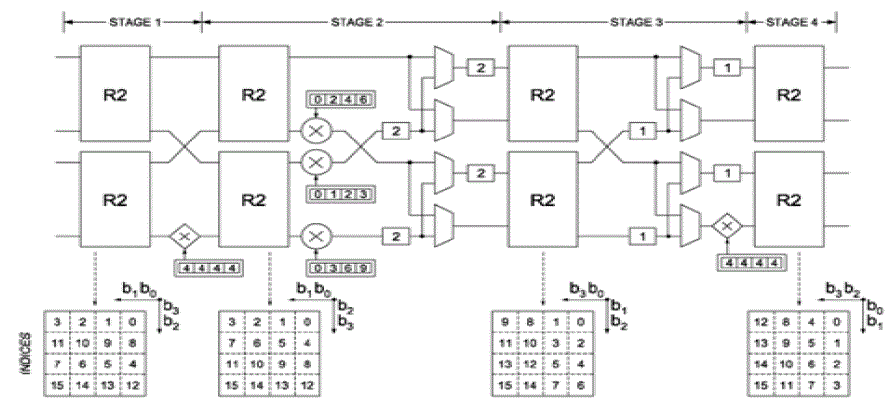
| The above diagram shows 4-parellel radix -2^2 feedforward architecture for decimation in frequency fast fourier
transform (DIF-FFT). This architecture processes 4 samples in parallel and can process the multiple input sequences
one after other to give the outputs. The order of the data shown at the bottom of each stage represents the order of
the data in which the data should be fed. The input should be given in the proper order as mentioned in the diagram
and the output will be obtained in the order mentioned in the diagram. |
| An important advantage of feedforward FFT architecture is 100% butterfly utilisation ratio. So it needs less number of
butterflies which means low area and low power. |
RADIX-2^K FEEDFORWARD FFT ARCHITECTURE |
| In Radix-2^k feedforward architecture, there are three possible rotations. They are trivial rotations, non-trivial
rotations and general rotations. |
| Trivial rotations are rotations for which the value of ω is either 0 or N/4 or N/2 or 3N/4 i.e. the samples must be
rotated by either 0 or 270 or 180 or 90 degrees. They are called trivial because these rotations can be done by
interchanging the real and imaginary parts and/or changing the sign of them. So, complex multiplication can be
avoided in implementing such rotations. Trivial rotation will be done at odd stages alone. |
| Non trivial rotations will be done only in even stages. In general, for higher values of „k” in radix-2^k feedforward
architecture, the non-trivial rotations can be simplified into rotations by W(8) and W(16), which include reduced
set of angles, and general rotations for remaining angles. These rotations by W(8) and W(16) can be simplified by
the use of trigonometric identities, scaling of coefficients and representation of the coefficients in canonical signed
digit (CSD). Rotations by W(8) consider only the angles of π/4. Rotations by W(16) consider only the angles of π/8.
For Radix-2^k feedforward FFT architecture, the type of rotation repeats every k stages. For example, radix 2^3
feedforward architecture requires non-trivial rotation every three stages. |
SPECIFICATIONS |
| The specifications of any P-parallel N-point radix-2^k feedforward architecture are shown below. |
| Number of parallel samples = P = 2^p |
| Number of butterflies = (P/2) * log N(base 2) = P * log N(base 4) |
| Number of complex adders = 2 * P * log N(base 4) = P * log N(base 2) |
| Number of rotators = ((3 * P)/4) * (log N(base 4) – 1) for P > 2 |
| 2 * (log N(base 4) – 1) for P = 2 |
| Throughput is the number of output samples obtained in unit time. |
| Throughput per clock cycle = P = Number of parallel samples |
| Latency is the time duration between the first input applied and the first output obtained i.e. it mentions the time taken by the system to process an input to give the respective output. |
| In the proposed architecture, latency = N / P |
| At any stage„s”, |
| Length of the buffer in shuffling structure L = N / 2^(s+1) |
| Total sample memory needed = N – P |
| Maximum memory needed to perform input reordering along with FFT = N – (N / P) |
| Maximum memory needed to perform output reordering along with FFT = N |
| Maximum memory needed to perform both input reordering and output reordering along with FFT = N |
| Where, |
| N is the number of inputs in a single sequence |
| P is the number of parallel input samples in the present stage of operation |
| Some other facts about feedforward architecture are |
| 1. Memory size will be same for any number of parallel samples. |
| 2. Both DIF FFT and DIT FFT require same number of hardware components |
| 3. Maximum memory needed is N, where N is the number of samples in an input sequence. |
| 4. Most suitable architecture will be selected based on the throughput and latency requirements of the required
applications. |
IMPLEMENTATION |
COMPONENTS |
RADIX-2 BUTTERFLY |
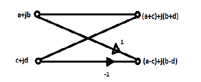
| The two inputs to the butterfly always differ in their rotation angle either by 0 or by N/4. Also at any stage„s”, the two
inputs which have indices differing only in the bit b(n-s) will be processed together in a butterfly. |
TRIVIAL ROTATION |
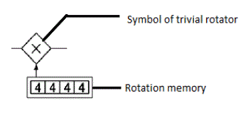
| Here the trivial rotation occurs only by N/4 i.e. complex multiplication by (-j). The basic operation of trivial rotation
can be performed by interchanging the real and imaginary components and/or changing the sign of them. |
NON-TRIVIAL ROTATION |
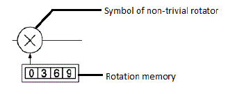
| Non trivial rotations will be done only in even stages. In decimation in frequency fast fourier transform, the
inputs with indices that satisfies b(n-s+1)+b(n-s)=1 will alone undergo non trivial rotation whereas in decimation in
time fast fourier transform, the inputs with indices that satisfies b(n-s-1)+b(n-s-2)=1 will alone undergo non trivial
rotation. |
DATA SHUFFLER |
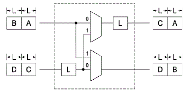
| Data shuffler consists of two components. They are buffers and multiplexers. In the diagram below, L denotes the
length of the buffer. For first L clock cycles, the multiplexer’s selection line will be set to 0. Then for next L clock
cycles, the selection line will be set to 1 and the change will happen simultaneously for every L clock cycles. |
| In the above diagram, for first L clock cycles, A will be stored in output buffer and C will be stored in input buffer.
For the consecutive L clock cycles, multiplexer’s select lines will be set to 1. So, B will be directly sent to the lower
output. The value A from the output buffer will be sent to the upper output. The value C will be moved from input
buffer to output buffer. The value D will be moved to the input buffer. Finally in output, A and B will be available in
the second clock cycle and C and D will be available in the next clock cycle. Thus, the inputs are shuffled to get the
desired order. The value of L is always a power of two. The control signals of the multiplexer can be directly
obtained from the bits of a counter. |
VHDL CODE |
| VHDL language is chosen for programming since it supports lot of loop operations and real operands. The
programming was done as a basic FSM (finite state machine) model. Initially, the entire circuit was divided into
seven blocks. Each individual block is checked for proper working and then, the blocks are grouped gradually in
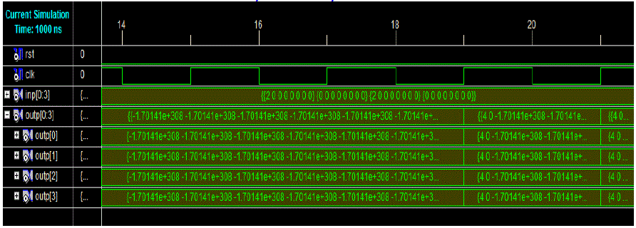
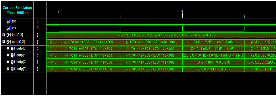
FSM model and they are checked and errors and logical mistakes were rectified. Then, the output was obtained for
a single sixteen point input sequence with a latency of nineteen. |
| Then, the blocks are combined in order to attain the theoretical latency i.e. latency = N/P = 4. It was observed that
each stage in FSM model takes one clock cycle for execution. So, it was concluded that the theoretical latency (in
this case, latency = 4) can be obtained only by reducing the entire circuit into a single block. |
ONGOING WORK ON DATA TYPE AND ROTATIONS` |
| The entire model is implemented in Xilinx 9.2i using real data type. But, the real data type can’t be synthesized and
hence netlist can’t be created. So, the change of data type from real to Q(m.n) format is being done. Q(22.10) is
selected in order to provide maximum accuracy. The two works to be done are, first a synthesized netlist is to be
obtained by implementing the code using Q(22.10) format and number of adders multipliers and memory are to be
analysed. The second one is to reduce non trivial rotations using different properties and thereby further reducing the
number of components needed to implement the architecture. |
CONCLUSION |
| Feedforward architecture saves more area than other architectures as N become larger. Also, feedforward architecture
is more efficient than parallel feedback architectures when several samples are processed in parallel. The proposed
design also achieves high throughput. Therefore, it is efficient in terms of both area and performance. Another advantage of the proposed architecture is that, the utilization ratio of the butterflies is 100%. So, no part of
architecture remains idle thereby performing the operation faster and reduce the power consumption and it requires
less number of components since it achieves 100% utilization ratio. Using this proposed architecture, it is possible to
attain the throughput in order of giga samples per second at very low latencies. |
ACKNOWLEDGEMENT |
| First, I want to thank god for his abundant grace which sustained me throughout the project. I want to thank my parents
who supported me with patience and encouragement. I want to thank my project guide Mr. M.
Mohamed Rabik, Asst.Professor of ECE department who has been supporting me with valuable guidance. I also
want to thank other staff members and friends who encourage me on this work. |
Tables at a glance |
 |
| Table 1 |
|
Figures at a glance |
 |
 |
 |
 |
| Figure 1 |
Figure 2 |
Figure 3 |
Figure 4 |
 |
 |
 |
| Figure 5 |
Figure 6 |
Figure 7 |
|
References |
- S-N. Tang, J-W. Tsai, and T.-Y. Chang, “A 2.4-GS/s FFT processor for OFDM-based WPAN applications,” IEEE Trans. Circuits Syst. I, Reg. Papers, vol. 57, no. 6, pp.451–455, Jun. 2010.
- M. A. Sánchez, M. Garrido, M. L. López, and J. Grajal, “Implementing FFT-based digital channelized receivers on FPGA platforms,” IEEETrans. Aerosp.Electron.Syst.,vol.44,no. 4,pp. 1567–1585,Oct2008.
- H. Liu and H. Lee, “A high performance four-parallel 128/64-pointradix-2^4 FFT/IFFT processor for MIMO-OFDM systems,” in Proc. IEEE Asia Pacific Conf. Circuits Syst., 2008, pp. 834–837.
- S.-I. Cho, K.-M. Kang, and S.-S. Choi, “Implemention of 128-point fast fourier transform processor for UWB systems,” in Proc. Int. Wirel. Commun. Mobile Comput. Conf., 2008, pp. 210–213.
- J. Lee, H. Lee, S. I. Cho, and S.-S. Choi, “A high-speed, low-complexity radix-2^4 FFT processor for MB-OFDM UWB systems,” inProc. IEEE Int. Symp. Circuits Syst.,2006, pp. 210–213.
- H.L. Groginsky and G.A. Works,“A pipeline fast Fourier transform,”IEEE Trans. Comput., vol. C-19, no. 11, pp. 1015–1019, Oct. 1970.
- http://www.eda-stds.org/fphdl/,http://www.eda-stds.org/fphdl/vhdl.html http://www.eda- stds.org/vhdl-200x/vhdl-200x-ft/packages_old/
- http://www.ens-lyon.fr/LIP/Arenaire/Ware/FPLibrary/
- http://cs.furman.edu/digitaldomain/more/ch6/dec_frac_to_bin.htm
- http://www.math.grin.edu/~rebelsky/Courses/152/97F/Readings/student-binary
|