ISSN ONLINE(2319-8753)PRINT(2347-6710)
ISSN ONLINE(2319-8753)PRINT(2347-6710)
1A.Gopichand, 2Dr.G.Krishnaiah, 3D.Krishnaveni, 4Dr.Diwakar Reddy.V
|
| Related article at Pubmed, Scholar Google |
Visit for more related articles at International Journal of Innovative Research in Science, Engineering and Technology
Steel Sandwich Plate Systems (SPS) have been used for commercial applications during the last 15 years. Stairs & staircase landings, bulkheads and decks are the main application areas of metallic sandwich panels in cruise ships and in other marine applications. In recent years a wide variety of applications of stainless steel sandwich panels are used in civil and mechanical engineering as well as in other industrial sectors. These include floors of buses, walls and floors of elevators, working platforms in industrial applications and balconies of shipyard. The sandwich structures have potential to offer wide range of attractive design solutions. The steel sandwich structure offer high strength to weight ratio, noise control, high stiffness etc if compared to traditional steel plate flows. In this work numerical simulation of SPS floor with all edges clamped, subjected to uniform pressure loading is carried out in ANSYS workbench. The SPS floor simulation results are compared with traditional steel plate of with same weight, same area with same boundary conditions and loading.
Keywords |
| Sandwich panels, ANSYS Workbench, Uniform pressure load, Sandwich plate system, Numerical simulation |
I. INTRODUCTION & LITERATURE REVIEW |
| A. Steel Sandwich panels |
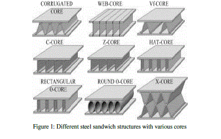
| Metallic Sandwich panels with top and bottom plates as well as the core made up of steel are called steel sandwich panels. The core structures are of different types according to core structures the steel sandwich structures are divided some of them are I-core, O- core with rectangular beams, Vf/V- core with hat or corrugated sheets as a core, web core, round O-core and X-core with two hats as a core as shown in figure 1 |
 |
| B. Application of Sandwich structures as floor |
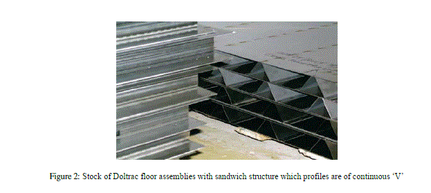
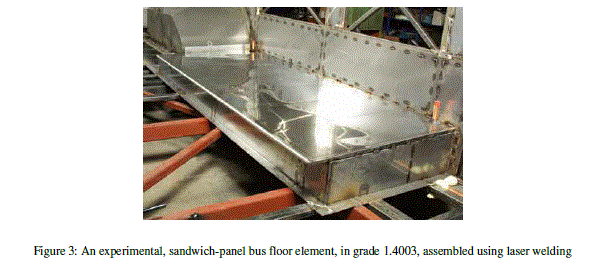
| Stainless steel can be used in a variety of ways in floors. The Doltrac floor is a stainless steel floor component with a sandwich structure. It has an upper face in 1.9 mm stainless steel sheet, and a 1.2 or 1.5 mm lower face, spaced either by rectangular sections 50 mm high (type O), or continuous or discontinuous inverted V sections (types V and Vf ). Figure 2 shows floor panels with inverted V sections. The components are assembled by gluing, or by continuous or spot laser welding. These floor components provide high stiffness for low weight. Figure 4 shows the all steel sandwich panel being used for bus floor. The use of ribbed sheets for permanent shuttering under a concrete slab is another solution, already tested in situ. The visual quality of stainless steel provides the designer with the possibility of leaving the metal sheet visible for ceilings thereby gaining free headroom by grouping cables and fluids in suspended trays. |
 |
 |
| C. Literature Review |
| Pentti Kujala made analysis on metallic sandwich panels which are laser welded have excellent properties with light weight having more applications[1] Jukka Säynäjäkangas make a review in design and manufacturing of stainless steel sandwich panels and conclude an efficient sandwich is obtained when the weight of the core is close to the combined weight of the both faces [2]Pentti Kujala discussed that steel sandwich panels that are welded by laser can save 30-50% weight compared to conventional steel structures [3]Romanoff & Kujala, investigated and related to design or design optimisation of steel sandwich panels for typical steel sandwich cross sections are studied[9].PenttiKujala, et al [11] investigated the applications of laser welded steel sandwich panels in marine application. China Classification Society released a document standardizing the guidelines for assessment of ship structures constructed using steel sandwich structures or other composite structures[13]. |
II. INTRODUCTION TO ANSYS WORKBENCH |
| ANSYS Workbench is a common platform for solving engineering problems. Typical tasks you can perform in Workbench are: |
| • Importing models from a variety of CAD systems. |
| • Conditioning models for design simulations using the Design Modeler. |
| • Performing FEA simulations using Simulation. |
| • Optimizing designs using Design Xplorer or Design Xplorer VT. |
| Different processors within ANSYS Workbench are |
| 1. Design Modeler |
| 2. Simulation |
| 3. DesignXplorer or DesignXplorer VT |
| 4. AUTO DYN |
| 5. CFX Mesh |
| 6. FE Modeler |
| Basically, you will use the Design Modeler to create the geometry and the Simulation to set up the materials, FE-mesh, loads and boundary conditions, solve the problem and analyse the results. The standard interface ANSYS Classic (used in the first computer workshop) is still the core of ANSYS. ANSYS Workbench is a new modern interface with more up to date functions such as, for example, the integration of CAD geometries. In this platform working on Multiphysics simulation is easy. Those performing a structural simulation use a graphical interface (called the ANSYS Workbench Mechanical application) that employs a tree-like navigation structure to define all parts of their simulation: geometry, connections, mesh, loads, boundary conditions and results. |
| Design Modeler |
| Design Modeler is designed to be used as a geometry editor of existing CAD models. Design Modeler is a parametric feature-based solid modeler designed so that you can intuitively and quickly begin drawing 2D sketches, modeling 3D parts, or uploading 3D CAD models for engineering analysis preprocessing. |
| SIMULATION Use the Workbench Simulation module to define your model's environmental loading conditions, solve the simulation, and review results in various formats depending on the type of simulation. |
| DesignXplorer – use this application to optimize a design using Design of Experiments (DOE) methodology. |
| AUTODYN – use this application to model short duration events involving large deformations or complete material failure as well as fluid solid interaction. |
| CFX Mesh – use this applications to generate a mesh that is used by the CFX program.CFX performs Computational Fluid Dynamics. |
| FE Modeler – use these applications to import a finite element model that was generated using the FEA program Nastran into Workbench |
III. NUMERICAL SIMULATION |
| A. Numerical Simulation of floor assembly. |
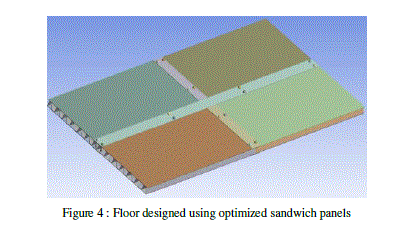
| A 3D model of sandwich floor is generated using Pro-E by assembling four sandwich panels . Face sheets and Core Material - Stainless steel 304 |
| Thickness of the face sheets – 18 gauge |
| Core shape – V |
| Core Height - 20 mm |
| Panel shape – Rectangular - 250 mm × 500 mm |
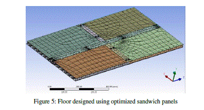
| The floor assembly is modelled in Pro-E and the model in igs format is imported to ANSYS Workbench as shown in figure 4. The solid element is considered for meshing as shown in figure 5. |
 |
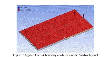
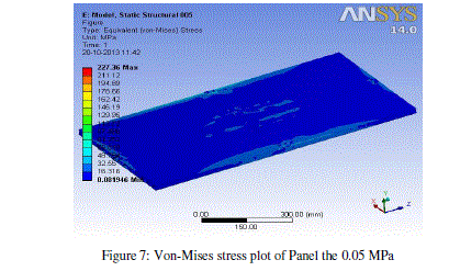
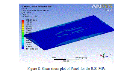
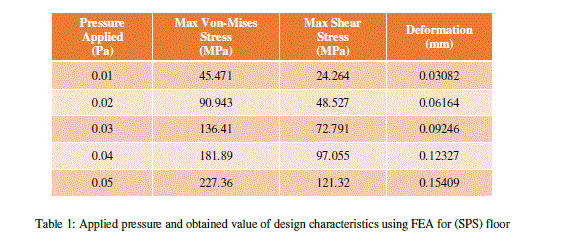
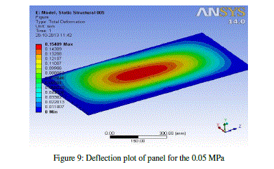
| All the edges of the floor are clamped and uniform pressure loading 0.01MPa, 0.02MPa, 0.03MPa, 0.04MPa, 0.05MPa are considered for the analysis. The applied loads & boundary conditions for the sandwich panel as shown in figure 6 The Design characteristics von-mises stress, maximum shear stress and Deformation for 0.05MPa are shown in figures 7,8 ,9. |
 |
 |
| B. Numerical Simulation for Rectangular plate floor: |
| A 3D model of a rectangular SS plate with surface area dimensions as that of sandwich floor but with thickness chosen such that the weight of the plate is equal to that of the sandwich floor is created in Pro/E. This plate model is then imported into Ansys. FEA is then performed on this model to study its behavior under the same loading and boundary conditions as that of the floor. A traditional steel plate of same weight and area, with same boundary conditions is considered for the analysis. The Design characteristics von-mises stress, maximum shear stress and Deformation for 0.05MPa are shown in figures 10, 11, 12. |
 |
 |
IV. RESULTS AND DISCUSSIONS |
| The table1 shows the obtained value of Design characteristics of the SPS floor for an applied pressure of 0.01MPa to 0.05MPa. The table2 shows the obtained value of Design characteristics of the plate floor for an applied pressure of 0.01MPa to 0.05MPa. |
 |
| A. Performance comparison of a Plane Plate Floor and All-Metal Sandwich Panel: |
| Comparative graphs for various design characteristics obtained from various simulations that were executed on sandwich floor (i.e. optimized SPS) and equivalent rectangular steel plate are presented in figures 7.7, 7.8 & 7.9. From the graphs, it can be observed that the stress levels are always lower in SPS floor when compared to the plate floor. Considering Von-Mises stresses (Figure 7.7), the distance between the plots is gradually increasing. At the lowest pressure, i.e. at 0.01MPa the stress in plate floor are more than that of SPS floor by a value of 11MPa while at the highest pressure the difference is around 55MPa indicating that the plate floors lower strength than when compared to that of SPS floors. |
 |
| From the comparative graph of ïÃÂä / l (Fig : 16), it can be seen that the deflection of SPS floor is around 72 times less than that of plate floor. Based on the results the stiffness of both SPS floors and plate floors is computed at max allowable loads. Stiffness of a plate is given by, |
 |
| Using the above relation, |
| Stiffness of SPS floor @0.05MPa, SPS k =162242.85 N/mm |
| Stiffness of Rectangular Plate floor @0.05MPa, RP k =2294.84 N/mm |
 |
| The above ratio indicates that by using SPS systems for floor design, the stiffness has increased by a factor of 70.7. |
References |
|