In this paper a project is proposed to separate the objects from a set according to their colour. This can be usefulto categorise the objects which move on a conveyer belt. The proposed method of categorisation is based on colour of the object. In this project the system categorise balls of three different colours. The detection of the particular colour is done by a light intensity to frequency converter method. The robotic arm is controlled by a microcontroller based system which controls DC servo motors.
Keywords |
| Robotic arm, Microcontroller, Light to frequency converter, DC servo motor. |
INTRODUCTION |
| Mainly the colour sorters are used in agricultural machineries like rice sorter, beans sorter, peanut sorter etc. Colour
sorters are used in other industrial applications also like quartz sand sorter, plastic granule sorting of coloured nuts and
bolts etc. It reduces the human effort, labour and cost. It also increases the efficiency since the mechanised sorting is
much faster the manual sorting.An ARM7 based microcontroller LPC2138, which is a 32 bit microcontroller with
RISC architecture is programmed to control the robotic arm. The TCS3200 light intensity-to-frequency converter
senses the colour and produce a square wave with varying frequency depends on the colour of the object to be picked
up. Four DC servo motors are used in the construction of the robotic arm.The arm of the robot is constructed using
aluminium brackets. Four types of brackets are designed for this purpose, two types for holding the servos and two
types for length extension and interconnections. The ball picking gripper which is controlled by a servo is attached and
the tip of the arm. |
LITERATURE SURVEY |
| To reduce human efforts on mechanical maneuvering different types of robotic arms are being developed. These arms
are too costly and complex due to the complexity and the fabrication process. Most of the robotic arms are designed to
handle repeated jobs. In design of the robotic are different parameters are to be taken care. The design of mechanical
structure with enough strength, optimum weight, load bearing capacity, speed of movement and kinematics are
important parameters. In electronic design the specification of the motors, drives, sensors, control elements are to be
considered. In the software side the reconfigurability, user interface and implementation and compatibility are to be
considered. |
| The paper prescribed in ref. [4] deals with the designing and implementation of Synchronized Robotic Arm, which is
used to perform all the basic activities like picking up objects and placing them. The robot interact with its by means of
arm and gripping device but there is no sensors. |
| The KUKA youBotis released their new 5-DOF arm with 2 finger gripper for educational and robotics research [8].
Camera is available as an accessory and the processing software has to be developed. There is no simple sensor which
is attached to it. The advantage with youBot is it operates on open source platform. |
| Regarding the control software for the robotic arm standard software are available. The CAD based drawing can be
used to manipulate the movement of the robotic arm and a CAM software can convert the drawing into motion
codes[5]. Currently many Open Source based software are also available for the CAD/CAM design. Linux CNC is one
of the popular open source CAD/CAM software. |
| A. Ramakrishna et.al. in ref [6] proposed a system to design and implement a robotic arm based on haptic technology.
The haptic feedback is mainly provided based on potentio meters and not through any highly sophisticated system. The
technology is having a serious problem in feedback and can be improved by using optical sensors at the arm. |
PROPOSED SYSTEM |
| The working model of the project is divided in to different sections like detection, control section, mechanical assembly
and working. |
| Different mechanisms can be used for detection of the object. For the trial run of the project the colour based detection
has been selected. Since the optical sensors are used without much processing of the input data the sensing is done at a
faster rate. The colour sensor itself provide direct signal to the microcontroller after detecting the object. The main
operation of the microcontroller is limited to servo motor control and the overall response is expected to be better. The
L293D driver ICs are used to drive the DC servo motors. The drivers are fast enough to deliver the pulses at required
speed to the motors. |
DESCRIPTION OF THE BLOCK DIAGRAM |
| A. COLOUR DETECTION |
| This section is used for detecting the colour of the balls to be sorted. There are many colour sensing ICs available
today. In different ICs the properties vary such as colour differentiating ability, output format, price, speed, resolution
etc. In this project TCS3200 is selected. |
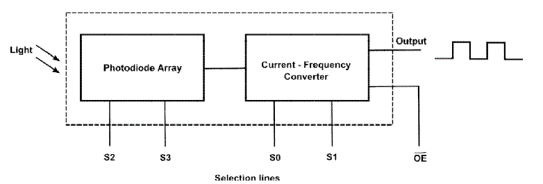
| The TCS3200 is a programmable light-to-frequency converter that combines configurable silicon photodiodes and a
current to frequency converter on a single monolithic CMOS integrated circuit. The output is a square wave (50% duty
cycle) with frequency directly proportional to light intensity. |
| The full-scale output frequency can be easily scaled by one of three values via two control input pins. Digital inputs
and digital outputs allow direct interface to a microcontroller or other logic circuitry. Output enable places the output in
the high impedance state for multiple-unit sharing of a microcontroller input line. In TCS3200, the light-to-frequency
converter reads an 8x8 array of photodiodes. Sixteen photodiodes have blue filters, Sixteen photodiodes have green
filters, Sixteen photodiodes have red filters, Sixteen photodiodes are clear with no filters. |
| The four types of photodiodes are interdigitated to minimize the effect of non-uniformity of incident irradiance. All
photodiodes of the same colour are connected in parallel. Pins S2 and S3 are used to select the group of photodiodes
(red, green, blue, clear) are active. Photodiodes are 110μm x110μm in size and are on 134μm centres. Outputfrequency
scaling is controlled by two logic input, S0 and S1. The internal light-to-frequency converter generates a
fixed-pulse width train. Scaling is accomplished by internally connecting the pulse-train output of the converter to a
series of frequency dividers. Divided outputs are 50% duty cycle square waves with relative frequency values of 100%,
20% and 2%. Because division of the output frequency is accomplished by counting pulses of the principal internal
frequency, the final output period represents an average of the multiple periods of the principle frequency. |
| B. MICROCONTROLLER |
| In this project ARM7 based microcontroller LPC2138 is used which is a 32 bit microcontroller with RISC architecture.
It has 48 I/O lines.The data output from TCS3200 is a waveform with 50% duty cycle and a frequency proportional to
the intensity of the light reflected from object. The frequency proportional to the intensity of the light reflected from
light. The frequency proportional to the of the waveform if calculated using the microcontroller by finding the time
elapsed between two successive high pulses which will give the time period of a pulse. The time thus obtained can be
substituted in mathematical equations which will give the frequency of the waveform. The time period elapsed between
two successive pulses is measured by using external interrupts, when a high pulse is appeared at the external interrupt
an interrupt is generated and corresponding ISR routine is executed. The first interrupt generated will start the timer.
The timer value will be inversely proportional to the frequency of the waveform,with a convenient relation the
respective frequency is calculated.Since the frequency of the waveform is proportional to the intensity if the reflected
light from the object which is very much related to the colour of the object and the colour of the object can be decoded
from the frequency of the pulse train. Once the colour of the ball is detected, the ball is picked up from the rail and
drops it in the right basket using the robotic arm. The robotic arm movement is anticipated by using servo motors.
Rotation of the servo motors converted to arm movement. That angle of rotation is based on the duty cycle of the
waveform appearing on the control pin of the servo motor and it remains in that position as long as the waveform
continues. The PWM for controlling the servo motors are generated by the microcontroller according to the colour
input to the servo motors are controlled by the different four output pins of the microcontroller. |
| C. ROBOTIC ARM STRUCTURE |
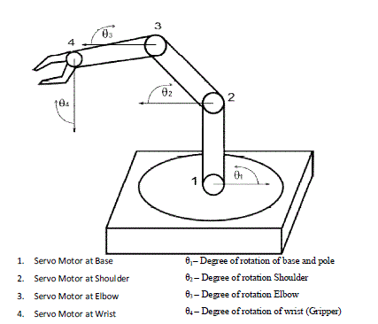
| The robotic arm is controlled using servo motors whose degree of rotation is controlled by the on timer of the pulse rail
appearing at its control input. According to the structure by the robotic arm various degree of rotation for the servo
motor are assigned to carry out the operations. |
| The arm of the robot is realized using aluminium brackets. Four types of brackets are designed for this propose. Two
types of the brackets are for holding the servo motors and two types for the extensions and interconnections of the
robotic arm. |
| D.WORKING |
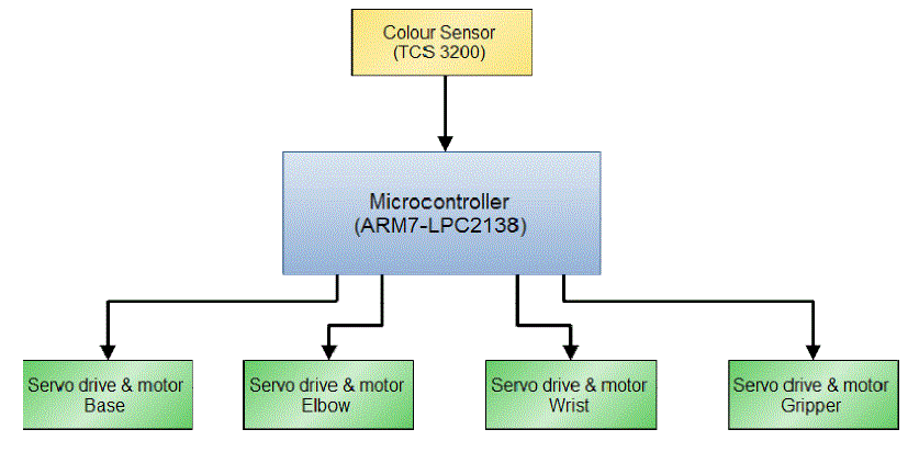
| The colour sensor identifies the colour of the ball and it sends the data to a microcontroller which controls the arm
motion according to the colour of the ball. The motion of the servo motors are controlled in a manner so that each ball
is dropped into a respective boxes place in a predetermined position. |
| The time taken by the robotic arm for a single motion is set to approximately 0.5 seconds. Eight steps of motion of
robotic arm are required for a ball to be picked up and to be dropped in the correct basket.That includes motion of arm
from the default position, picking a ball, motion to the correct basket, dropping the ball to the basket and return to the
default position. The number of steps taken by the arm to pick the ball and drop the ball counts to seven steps and from
there to back to default position needed one step. Approximate time needed for the microcontroller to identify colour of
the ball is around one second. Therefore the total time needed for picking and dropping the ball including identifying
the colour is around five seconds. |
| Four motors are used in the robotic arm. One to control the rotational motion of the base, one to control the angle at the
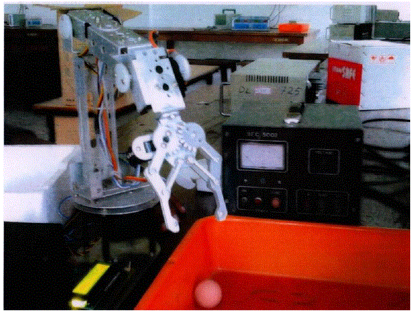
elbow, one to control the wrist movement and last one to control the gripper, that is to hold and drop the ball. The
figure 3 shows the initial position of the robotic arm when power is applied and the robot is ready for operation. |
| A lever mechanism is used for opening and closing the gripper. So a single motor is enough for the gripper control.
Fingers come closer to pick and hold the ball and move apart when it drops the ball. Two positions are designed for the
fingers by using a single servo motor. One in close position and the other in open position. Two motions are permitted
for the motors at wrist and elbow that is to move up and down. |
| Then by controlling the finger motion the ball is picked. After picking the ball arm return back to initial position by
rotating motor at the wrist and elbow to default degrees. Here only one position of servo motor at finger varies from
default position and the position of the motor. The motion of the motor at the base is controlled as per the colour of the
ball. The base motor is made to rotate to four different positions. One is the default position which keeps the arm
directly above the sensor module. Other three motions keep the arm above the appropriate colour boxes. Two boxes are
placed left to the base, one at extreme left and the other one located between extreme left and default position and one
box at the right. Angle of rotation of the base motor for each motion is described below Consider the colour of the ball is red and ball is to be dropped in the box at the right side. The rotation of the base
motor is based on the colour of the ball picked up. The value of the degree assigned to the base changes according to
the ball colour and the arm position itself above the right box to which the ball is to be dropped.Now the ball is to be
dropped. The ball is dropped in the correct box and now it has to be return to the initial position to pick up the next ball.
Base motor rotates CCW and the arm will be in the default position. |
RESULTS AND DISCUSSION |
| This paper presents the design, development and construction of a robotic arm, which can pick and sort objects of
different colour. The mechanical structure of the robot was assembled using aluminium brackets which helped to
reduce the weight without losing the mechanical strength. The aim of the project was to have a fully functional robotic
arm which sorts different coloured balls and the target is achieved successfully. In the final run of the project red,
yellow and green balls were successfully sorted. The colour sensor IC TCS3200show almost stable response in various
sunlight conditions. |
| The system is working with open loop. A better resolution can be achieved if closed loop control is incorporated. The
system responses are a little bit slower than expected. It can be improved by using a more advanced colour sensor and
microcontroller. User interfaces also can be provided as a modification which will enable the on demand
reconfiguration of the movement in a better way. |
CONCLUSION |
| The aim of the project was to have a fully functional robotic arm which sorts different coloured balls and the target is
achieved successfully. In the final run of the project red, yellow and green balls were successfully sorted. The colour
sensor IC TCS3200show almost stable response in various sunlight conditions. |
| The system is working with open loop. A better resolution can be achieved if closed loop control is incorporated. The
system responses are a little bit slower than expected. It can be improved by using a more advanced colour sensor and
microcontroller. |
Tables at a glance |
 |
| Table 1 |
|
Figures at a glance |
 |
 |
 |
 |
| Figure 1 |
Figure 2 |
Figure 3 |
Figure 4 |
|
References |
- T N. Tsagarakis, M. Laffranchi, B. Vanderborght, and D. Caldwell, “Acompact soft actuator unit for small scale human friendly robots”, IEEE International Conference on Robotics and Automation Conference(ICRA), pp. 4356–4362, 2009
- Edsinger-Gonzales and J. Weber,“Domo: A force sensing humanoid robot for manipulation research,” in 2004 4th IEEE/RASInternational Conference on Humanoid Robots, pp. 273–291, 2004.
- Ashraf Elfasakhany, Eduardo Yanez, Karen Baylon, Ricardo Salgado,”Design and Development of a Competitive Low-Cost Robot Arm with Four Degrees of Freedom”, Modern Mechanical Engineering, 1, pp: 47-55, 2011.
- GoldyKatal, Saahil Gupta, ShitijKakkar,”Design And Operation Of Synchronized Robotic Arm”, International Journal of Research in Engineering and Technology, Volume: 02 Issue: 08, Aug-2013.
- ShwetaPatil, Sanjay Lakshminarayan,”Position Control of Pick and Place Robotic Arm”,EIE’s 2nd Intl’ Conf.Comp., Energy, Net., Robotics and Telecom. EIE Con2012.
- Rama Krishna, G. SowmyaBala, A.S.C.S. Sastry, B. BhanuPrakashSarma, GokulSaiAlla,” Design And Implementation Of A Robotic Arm Based On Haptic Technology”, International Journal of Engineering Research and Applications. Vol. 2, Issue 3, pp.3098-3103, May-Jun 2012.
- Ahmed M. A, Haidar1, Chellali, Benachaiba2, Mohamad, Zahir, ” Software Interfacing of Servo Motor with Microcontroller”, Journal of Electrical Systems, 9-1, pp 84-99, 2013.
- KUKA, “youbot arm,” Available: http://www.youbot-store.com. [Online]. 2010.
- Nathaniel Pinckney, “ Pulse-width modulation for microcontroller servo motor”, IEEE , 2006.
- Morgan Quigley, Alan Asbeck, Andrew Y. Ng, “A Low-cost Compliant 7-DOF Robotic Manipulator,”
|