The paper presents a smart approach for a real time inspection and selection of objects in continuous flow. Image processing in today’s world grabs massive attentions as it leads to possibilities of broaden application in many fields of high technology. The real challenge is how to improve existing sorting system in the modular processing system which consists of four integrated stations of identification, processing, selection and sorting with a new image processing feature. Existing sorting method uses a set of inductive, capacitive and optical sensors do differentiate object color. This paper presents a mechatronics color sorting system solution with the application of image processing. Image processing procedure senses the objects in an image captured in real-time by a webcam and then identifies color and information out of it. This information is processed by image processing for pick-and-place mechanism. The sorting process is based on a 2 phase operative methodology defined 1) a self-learning step where the apparatus learns to identify objects ; 2) an operative selection process where objects are detected, classified using a decisional algorithm and selected in real time. The Project deals with an automated material handling system. It aims in classifying the colored objects by colour, size, which are coming on the conveyor by picking and placing the objects in its respective pre-programmed place. Thereby eliminating the monotonous work done by human, achieving accuracy and speed in the work. The project involve sensors that senses the object’s colour, size and sends the signal to the microcontroller. The microcontroller sends signal to circuit which drives the various motors of the robotic arm to grip the object and place it in the specified location. Based upon the detection, the robotic arm moves to the specified location, releases the object and comes back to the original position [1] [2].
Keywords |
| Robotic System; Micro-controller; Camera; Conveyor belt system; Servomotor; Image Processing, PC. |
I.INTRODUCTION |
| Determining real time and highly accurate characteristics of small objects in a fast flowing stream would open new
directions for industrial sorting processes. The present paper relates to an apparatus and method for classify in and
sorting small-sized objects, using elect ronic systems and advanced sensors operating on the basis of a physical and
geometric characterization of each element. Recent advances in electronics and printed circuit board technology open
new perspectives for industrial application in this field. The proposed selection process is based on a multisensorial
characterization, and more specifically on crossed optical and impedimetric analysis of the objects to be sorted. Parallel
guides, also called channels, are created on a slanted plant support. The objects to be sorted are immersed in a
continuous, free-falling flow along said guides [1] [2]. By another way this project can be treated an automated material
handling system & can be designed by following way. It synchronizes the movement of robotic arm to pick the objects
moving on a conveyor belt. It aims in classifying the coloured objects which are coming on the conveyor by picking
and placing the objects in its respective pre-programmed place. Thereby eliminating the monotonous work done by
human, achieving accuracy and speed in the work. The project involves colour sensors that senses the object’s colour
and sends the signal to the microcontroller. The microcontroller sends signal to circuit which drives the various motors
of the robotic arm to grip the object and place it in the specified location. Based upon the colour detected, the robotic
arm moves to the specified location, releases the object and comes back to the original position [1][2]. |
II.SYSTEM MODEL AND ASSUMPTIONS |
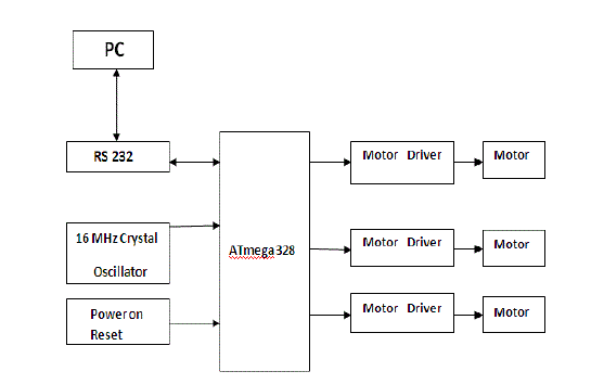
| The fig. shows block diagram of a system. The basic theme of this project is object flowing on conveyor are sensed,
selected and sorted depending on their colour and size. For this, camera used as input sensor, camera is overhead
camera which will be mounted on PC, and will be connected to PC by USB. The camera will take a snap and it will
feed to PC for colour processing. In PC matlab is used for processing on colour, depending on this signal will be given
to microcontroller Atmega 328. The microcontroller in turn will control the servomotors by PWM signals. These
servomotors will control the movement of robotic arm, by controlling their angular movement. Thus the robotic arm will be fully controlled by servomotors. The gripper of robotic arm will pick the object place it depending on its size.
This is full automatic process no manual support is needed. The microcontroller used here is with the support of
Arduino kit. The Arduino is good platform for robotics application. It is the software and hardware also, using both the
above system is developed. Thus the real time, continuous object sorting can be done. |
| A. Microcontroller |
| The ATmega328 is a low-power CMOS 8-bit microcontroller based on the AVR enhanced RISC architecture. By
executing powerful instructions in a single clock cycle, the Atmega 328 achieves throughputs approaching 1 MIPS per
MHz allowing the system designer to optimize power consumption versus processing speed.The AVR core combines a
rich instruction set with 32 general purpose working registers. All the 32 registers are directly connected to the
Arithmetic Logic Unit (ALU), allowing two independent registers to be accessed in one single instruction executed in
one clock cycle. The resulting architecture is more code efficient while achieving throughputs up to ten times faster
than conventional CISC microcontrollers. The Atmega 328 provides the following features: 4K/8Kbytes of In-System
Programmable Flash with Read-While-Write capabilities, 256/512/512/1Kbytes EEPROM, 512/1K/1K/2Kbytes
SRAM, 23 general purpose I/O lines, 32 general purpose working registers, three flexible Timer/Counters with
compare modes, internal and external interrupts, a serial programmable USART, a byte-oriented 2-wire Serial
Interface, an SPI serial port, a 6-channel 10-bit ADC (8 channels in TQFP and QFN/MLF packages), a programmable
Watchdog Timer with internal Oscillator, and five software selectable power saving modes. The Idle mode stops the
CPU while allowing the SRAM, Timer/Counters, USART, 2-wire Serial Interface, SPI port, and interrupt system to
continue functioning. The Power-down mode saves the register contents but freezes the Oscillator, disabling all other
chip functions until the next interrupt or hardware reset. In Power-save mode, the asynchronous timer continues to run,
allowing the user to maintain a timer base while the rest of the device is sleeping. The ADC Noise Reduction mode
stops the CPU and all I/O modules except asynchronous timer and ADC, to minimize switching noise during ADC
conversions. In Standby mode, the crystal/resonator Oscillator is running while the rest of the device is sleeping. This
allows very fast start-up combined with low power consumption.The 16 MHz Crystal Oscillator module is designed to
handle off-chip crystals that have a frequency of 16 MHz. The crystal oscillator output is fed to the System. As an
alternative to using a crystal, you can use an externally generated 16 MHz clock source as input tothe on-chip 16 MHz
oscillator. |
| B. Camera |
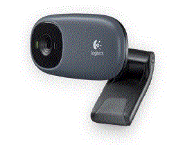
| The camera used in this case will be overhead camera, it will take the snapshot of the object for colour sensing purpuse. |
| The image captured by the camera will be processed by image processing using matlab. |
| The camera used in this case is Logitech PN 960-000748 whose technical specifications are: |
| • Video calling (640 x 480 pixels) |
| • Video capture: Up to 1024 x 768 pixels |
| • Fluid Crystal Technology |
| • Photos: Up to 1.3 megapixels (software enhanced) |
| • Built-in mic with noise reduction |
| • Hi-Speed USB 2.0 certified (recommended) |
| • Universal clip fits laptops, LCD or CRT monitors |
| C. Matlab and Image Processing |
| The name MATLAB stands for Matrix Laboratory. MATLAB was written originally to provide easy access to matrix
software developed by the LINPACK (linear system package) and EISPACK (Eigen system package) projects.
MATLAB is a high-performance language for technical computing. It integrates computation, visualization, and
programming environment. Furthermore, MATLAB is a modern programming language environment: it has
sophisticated data structures, contains built-in editing and debugging tools, and supports object-oriented programming.
These factors make MATLAB an excellent tool for teaching and research. MATLAB has many advantages compared
to conventional computer languages (e.g., FORTRAN) for solving technical problems. MATLAB is an interactive
system whose basic data element is an array that does not require dimensioning. The software package has been
commercially available since 1984 and is now considered as a standard tool at most universities and industries
worldwide. It has powerful built-in routines that enable a very wide variety of computations. It also has easy to use
graphics commands that make the visualization of results immediately available. Specie applications are collected in
packages referred to as toolbox. There are tool boxes for signal processing, symbolic computation, control theory,
simulation, optimization, and several otherof applied science and engineering [17]. Image can be assumed as the
visualization of what vision senses that is captured by camera. Image is considered as a two dimensional function with
variables that represent the spatial coordinate. It holds information about color as well as shapes. In color image, RGB
color model mixes those three prime color components, red, green and blue, to produce another color. Image capturing
and processing have been used widely in diverse applications, such in medical and surveillance applications. |
| D. Arduino |
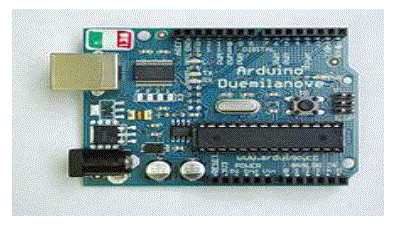
| Arduino is a tool for making computers that can sense and control more of the physical world than your desktop
computer. It's an open-source physical computing platform based on a simple microcontroller board, and a
development environment for writing software for the board. Arduino can be used to develop interactive objects, taking
inputs from a variety of switches or sensors, and controlling a variety of lights, motors, and other physical outputs.
Arduino projects can be stand-alone, or they can be communicating with software running on your computer (e.g.
Flash, Processing, MaxMSP.) The boards can be assembled by hand or purchased preassembled; the open-source IDE
can be downloaded for free. The Arduino programming language is an implementation of Wiring, a similar physical
computing platform, which is based on the Processing multimedia programming environment. An Arduino board
consists of an 8-bit Atmel AVR microcontroller with complementary components to facilitate programming and
incorporation into other circuits. An important aspect of the Arduino is the standard way that connectors are exposed,
allowing the CPU board to be connected to a variety of interchangeable add-on modules (known as shields). Most
boards include a 5 volt linear regulator and a 16 MHz crystal oscillator. The Arduino board exposes most of the
microcontroller's I/O pins for use by other circuits. It provides 14 digital I/O pins, six of which can produce PWM
signals, and six analog inputs. These pins are on the top of the board, via female 0.1 inch headers. Several plug-in
application "shields" are also commercially available [13]. There are many other microcontrollers and microcontroller
platforms available for physical computing. Parallax Basic Stamp, Netmedia's BX-24, Phidgets, MIT's Handy board,
and many others offer similar functionality. All of these tools take the messy details of microcontroller programming
and wrap it up in an easy-to-use package. Arduino also simplifies the process of working with microcontrollers, but it
offers some advantage for teachers, students, and interested amateurs over other systems: |
| Inexpensive -The least expensive version of the Arduino module can be assembled by hand, and even the preassembled
Arduino modules cost less than $50 |
| Cross-platform - The Arduino software runs on Windows, Macintosh OSX, and Linux operating systems.
Most microcontroller systems are limited to Windows. |
| Simple, clear programming. |
| Open source and extensible software- The Arduino software is published as open source tools, available for
extension by experienced programmers. The language can be expanded through C++ libraries. |
| Open source and extensible hardware - The Arduino is based on Atmel's ATMEGA8 and ATMEGA168
microcontrollers. |
| The Arduino Nano, and Arduino-compatible Bare Bones Board and arduino boards may provide male header pins on
the underside of the board to be plugged into solder less breadboards. The Arduino IDE is a cross-platform application
written in Java, and is derived from the IDE for the Processing programming language and the Wiring project. It is
designed to introduce programming to artists and other newcomers unfamiliar with software development. It includes a
code editor with features such as syntax highlighting, brace matching, and automatic indentation, and is also capable of
compiling and uploading programs to the board with a single click. There is typically no need to edit makefiles or run
programs on a command-line interface. Although building on command-line is possible if required with some thirdparty
tools such as Ino. There are a great many Arduino-compatible and Arduino-derived boards. |
| Some are functionally equivalent to an Arduino and may be used interchangeably. Many are the basic Arduino with the
addition of commonplace output drivers, often for use in school-level education to simplify the construction of buggies
and small robots. Others are electrically equivalent but change the form factor, sometimes permitting the continued use
of Shields, sometimes not. Some variants even use completely different processors, with varying levels of
compatibility. |
| E. Robotic Arms operated by Servomotors |
| Arms are types of jointed robot manipulator that allow robots to interact with their environment. Many have onboard
controllers or translators to simplify communication, though they may be controlled directly or in any number of ways.
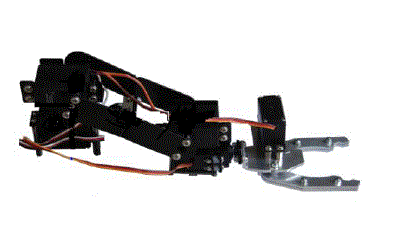
Due to this fact, standalone arms are often classified as full robots. The robot used in this project is 4 Axis Robotic
Arm. 4 Axis Robotic Arm is designed for small mobile robots. It can grip objects with the size up to 60mm with the
force up to 250gms. Arm has reach of 23cm. It can lift the payload up to 400gms. Robotic Arm comes fully assembled
and ready to use. First two axis of the arm are made up of NRS-995 dual bearing heavy duty metal gear motors and
remaining 2 axis and gripper uses NRS-585 dual bearing plastic gear servo motors. Axis 2 and 3 enables gripper to
maintain its angle constant with the surface while moving up and down. Robotic arm can do Left-Right, Up-Down
while keeping gripper parallel to surface, Twist motions and Gripping action. Robotic Arm will require current up to
5Amps. Make sure that your robot can supply that much amount of current for proper operation of the arm. The robotic
arm has following specifications. |
| Number of Axis: 4 + Gripper |
| Gripping force: 250gms (Maximum) |
| Gripping jaw length: 43mm |
| Gripping jaw width: 60mm |
| Weight: 541gms (Including 2 NRS-995 and 3 NRS-585 servo motors) |
| Operating voltage: 5V to 6V |
| Reach: 23cm |
| F. Servomotor |
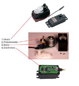
| Servos are DC motors with built in gearing and feedback control loop circuitry. And no motor drivers required. A
servomotor is a rotary actuator that allows for precise control of angular position. They consist of a motor coupled to a
sensor for position feedback, through a reduction gearbox. They also require a relatively sophisticated controller, often
a dedicated module designed specifically for use with servomotors. Servomotors are used in applications such as
robotics, CNC machinery or automated manufacturing. . The servo motor has some control circuits and a potentiometer
(a variable resistor) that is connected to the output shaft. This pot allows the control circuitry to monitor the current
angle of the servo motor. If the shaft is at the correct angle, then the motor shuts off. If the circuit finds that the angle is
not correct, it will turn the motor the correct direction until the angle is correct. The output shaft of the servo is
capableof traveling somewhere around 180 degrees. Usually, its somewhere in the 210 degree range, but it varies by
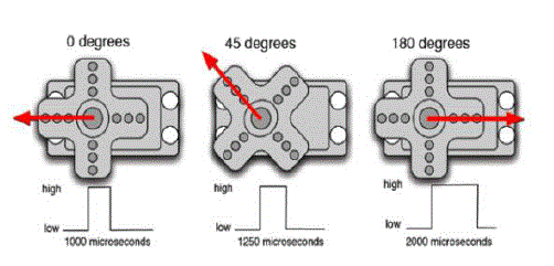
manufacturer. A normal servo is used to control an angular motion of between 0 and 180 degrees. A normal servo is
mechanically not capable of turning any farther due to a mechanical stop built on to the main output gear. The amount
of power applied to the motor is proportional to the distance it needs to travel. So, if the shaft needs to turn a large
distance, the motor will run at full speed. If it needs to turn only a small amount, the motor will run at a slower speed
[14] [15] [16]. |
| This is called proportional control. As the name suggests, a servomotor is a servomechanism. More specifically, it is a
closed-loop servomechanism that uses position feedback to control its motion and final position. The input to its control
is some signal, either analogue or digital, representing the position commanded for the output shaft. The motor is paired
with some type of encoder to provide position and speed feedback. In the simplest case, only the position is measured.
The measured position of the output is compared to the command position, the external input to the controller. If the
output position differs from that required, an error signal is generated which then causes the motor to rotate in either
direction, as needed to bring the output shaft to the appropriate position. As the positions approach, the error signal
reduces to zero and the motor stops.The very simplest servomotors use position-only sensing via a potentiometer and
bang-bang control of their motor; the motor always rotates at full speed (or is stopped). This type of servomotor is not
widely used in industrial motion control, but they form the basis of the simple and cheap servos used for radiocontrolled
models. More sophisticated servomotors measure both the position and also the speed of the output shaft.
They may also control the speed of their motor, rather than always running at full speed. Both of these enhancements,
usually in combination with a PID control algorithm, allow the servomotor to be brought to its commanded position
more quickly and more precisely, with less overshooting. The servo turn rate, or transit time, is used for determining
servo rotational velocity. This is the amount of time it takes for the servo to move a set amount, usually 60 degrees. For
example, suppose you have a servo with a transit time of 0.17sec/60 degrees at no load. |
| This means it would take nearly half a second to rotate an entire 180 degrees. More if the servo were under a load. This
information is very important if high servo response speed is a requirement of your robot application. It is also useful
for determining the maximum forward velocity of your robot if your servo is modified for full rotation. Remember, the
worst case turning time is when the servo is at the minimum rotation angle and is then commanded to go to maximum
rotation angle, all while under load. This can take several seconds on a very high torque servo. |
| G. Conveyor Belt |
| The conveyor motor receives power and signal from the central supply through rectifier and control circuit. The control
circuit consisting of a potentiometer will allow the user to manually control the speed of conveyor belt by the
regulatory knob. Polyester is used as a belt material. A conveyor belt consists of two or more pulleys, with a
continuous loop of material - the conveyor belt - that rotates about them. One or both of the pulleys are powered,
moving the belt and the material on the belt forward. The powered pulley is called the drive pulley while the unpowered pulley is called the idler. There are two main industrial classes of belt conveyors; those in general material
such as those moving boxes along inside a factory and handling such as those used to transport industrial and
agricultural materials, such as grain, coal, ores, etc. generally in outdoor locations. Standard gravity conveyor frame are
used overall. Conveyor frames are supplied with either butting plate (standard) or hook and bar attachments to secure
each segment together. Standard frames are supplied in a hammer tone blue spray painted finish oats or conditions.
Stainless steel rollers for wash-down or corrosive applications are used. Spring loaded axles slot into holes along the
frame. This allows for easy replacement of damaged rollers. Heavy duty rollers are supplied with shafts. Precision
or stainless steel bearings are available for frame work . Two types of standard supports are available. Both styles
provide adjustment. Other support styles and complete frames are used to special support. RHS Supports are bolted to
the underside of the conveyor frame via a crescent plate. This plate provides allowance for any angular misalignment.
Pipe stands are also available for economy or for applications where the conveyor may be moved on a frequent
basis. Normally, supports are only placed on every conveyor join 3 stands for 2frames [2]. |
III. APPLICATIONS |
| The system has many applications in various fields, as this system provides the sorting of objects, in flow of objects by
multisensing. Mainly this finds the important application in agriculture field where it can be used to sort the different
agriculture products like grains, lemons, almonds, grapes, and many more. For human beings it becomes comber sum
task to sort out the objects with high quality also the possibility of accuracy is less. In industry it can be used for
sorting of various objects, tools, with high degree of accuracy and quality with an automation. By this way the
proposed project can be used. It finds application in enormous way in agriculture, industry. |
IV. ADVANTAGES AND DISADVANTAGES |
| The main advantages of the proposed approach rely on the high discriminatory capacity of the object classes and on the
high degree of parallelism, capable of processing large amounts of material on production lines. The use of modern
electronic systems also allows high operative speed, easy calibration and flexibility (due to a programmable sorting
algorithm) to the required classification features. It has high efficiency with higher quality of sorting. It has high
sensitivity and ability to distinguish between the objects. It will be always better than human sorting. Some of the
prominent advantages are- |
| High efficiency: the sorting speed can be very high. |
| High precision: the margin of error can be reduced to great extent. |
| This type of sorter can be used for various objects or vegetables of different colors. Also suit to select pears,
orange and other fruits of this kind. |
| High degree of intelligence if used with PLC control. The machine with a high degree of intelligent , can
control it. |
| Good quality and low failure rate with long life. |
| Reliable operation and maintenance. |
V. CONCLUSION |
| Fully functional sorter machine can be implemented by using a structure of parallel and independent channels in order
to increase the overall throughput which results with a forecasted performance. The project can work successfully and
separates different objects using sensors. The sensor handling systems which drive the pick and place robot to pick up
the object and place it into its designated place can work if accurately designed. There are two main steps in sensing
part, objects detection and recognition. The system can successfully perform handling station task, namely pick and
place mechanism with help of sensor. Thus a cost effective Mechatronics system can be designed using the simplest
concepts and efficient result can be observed. |
Tables at a glance |
 |
| Table 1 |
|
| |
Figures at a glance |
 |
 |
 |
| Figure 1 |
Figure 2 |
Figure 3 |
 |
 |
 |
| Figure 4 |
Figure 5 |
Figure 7 |
|
| |
References |
- Alessandro Golfarelli, RossanoCodeluppi and Marco Tartagni, ― A Self-Learning Multi-Sensing Selection Process: Measuring Objects One by One by‖,ARCES – LYRAS LAB University of Bologna, Campus of Forlì, 1-4244-1262-5/07/$25.00 ©2007 IEEE, IEEE SENSORS 2007 Conference.
- Sahu, S., Lenka, P.; Kumari, S.; Sahu, K.B.; Mallick, B.; ―Design a colour sensor: Application to robot handling radiation work‖, Vol. 56, No. 10, pp. 365- 368, 2007, Industrial. Engineering.
- www.google.com/microepsilon.com/catcolorsensor—e
- www.shortcourse.com/www.sensors.com/optical/imagesensors
- wwwgoogle.com/wisegeek.com/whatis optical sensors.htm
- www.google.com/osa.org/sensors
- www.pdfgenicom/compacsort.com/sorters
- www.pdfgenicom/indiamart.com/sorting machine
- www.google.com/ATMEGA 48A/PA/328/P/DATASHEET SUMMARY
- www.google.com/zimbio.com/clip-base cam
- www.google.com/pdfsb.com/smps
- www.google.com/pdfgeni.com/vermnlstweb.nl
- www.google.com/arduino.cc/main/software
- www.google.com/eyantra.org/home/project
- Project on― Pick n Place Robot‖, made by Bharat Jain and Dinesh Rajput, under guidance of Prof.KaviArya, IIT Mumbai,2010.
- www.pdfgeni.com/servo-tutorial
- www.pdfgeni.com/matlab- mathematical lab/pdf
|