Keywords |
| BLDC motor drive, hysteresis controller, fault detection, fault tolerance. |
I. INTRODUCTION |
| BLDC motors have become more popular now a days. BLDC motors are electronically commutated motors so that
it has several advantages over ordinary brushed dc motor. These motors are normally reliable and more efficient. These
motors have noiseless operation, good dynamic response, long life and they are less affected by adverse climatic
conditions. Also their torque to size ratio is high which makes them applicable where space and weight are critical
factors. They are mainly used in industries like automotive industries, aerospace, military & robotic applications and
medical & consumer automation equipment’s and instruments. |
| As these motors are mostly used in high risk areas like military services, robotics, aerospace, etc. continuous
operation is required every time. So the occurrence of fault should not affect the normal working of motor. The
detection and identification of fault and its remedy thus gain attention. In this paper the open phase fault detection and
identification method using a simple logical technique is proposed. This method is cost effective and can be used in
speed controlled BLDC motor. The remedial strategy includes the working of motor using a four level inverter.Several
such detection techniques and the modeling of motor are proposed in [1-7]. Fault tolerant ripple free Model for BLDC
motor based on Fourier coefficients are explained in [1]. Based operating characteristics the fault detection explained in
[3]. Remedial strategies for BLDC faults are explained in [6]. Four switch inverter drives is explained in [7]. This paper
detects the fault and identifies it and a remedial model which is working on two level inverter. |
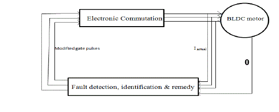
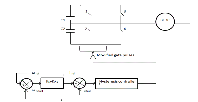
| The fault tolerant model is simulated using MATLAB – Simulink software. The entire fault tolerant model is
represented as a block diagram in fig.1 |
II. MODELLING OF SPEED CONTROLLED BLDC MOTOR. |
| A. Modelling of BLDC motor |
| The three phase star connected BLDC motor drives are governed by the following equations. |
 (1) (1) |
 (2) (2) |
 (3) (3) |
| Where ea, eb, ec are back emf of motor which is the function of rotor position. Also the torque equations are
given by |
 (4) (4) |
 (5) (5) |
 (6) (6) |
 (7) (7) |
| The parameters used in this modeling are |
| B. Modeling of normal speed controlled BLDC motor |
| From the rotor position the actual speed is compared with a set speed. The error is given to PI controller. The output
of the controller is the torque reference. Current is calculated from the torque reference and it is compared with actual
currents. By tuning the Kp and Ki values the error in the current is made to zero. Then a hysteresis current controller is
used to generate gate pulses to the six step inverter. |
 (8) (8) |
| The Simulink model uses a PI controller and their tuning results in controlled performace. |
III. FAULT TOLERANT CONTROL OF BLDC MOTOR |
| A. Fault Detection and Identification of BLDC motor |
| The major faults commonly occurring in a BLDC motor are stator faults like open circuit and short circuit faults, air
gap irregularities, dynamic eccentricity, broken end rings etc. In this paper only open phase fault is considered as it is
30-35% of all faults. |
| The fault is detected using a simple logical approach. The open phase fault is easily calculated by comparing the
currents in each phase. For normal working the absolute values of three phase currents is around three times each phase
value. But in single phase fault it reduces to double times or less than three times phase value. For fault detection a
threshold value and a residual value of currents are calculated.The threshold value is a function of reference value and
the residual value is the sum of absolute values of each phase current. |
 (9) (9) |
| Under faulty condition the reference value is not strictly double times the reference value. So a constant gf is introduced. |
| where gf is a constant whose value can be varied between 0 and 0.5. Above that the system becomes more unstable. |
 (10) (10) |
| Using the above two equations a comparison is made to detect fault in system. |
 (11) (11) |
 (12) (12) |
| This logic is implemented using MATLAB embedded function. |
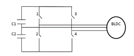
| The current and voltage across the inverter switch is measured and displayed continuously. When fault is detected
the current across open faulty switch become zero and voltage become dc link voltage. The faulty phase is thus
identified and then connected to the midpoint of capacitor. Thus the faulty switch is identified and the remedy circuit
gets activated.
. |
| B. Fault tolerant model |
| After the identification of faulty phase, modified gate pulses are given to other two phases for the normal working
of drive. |
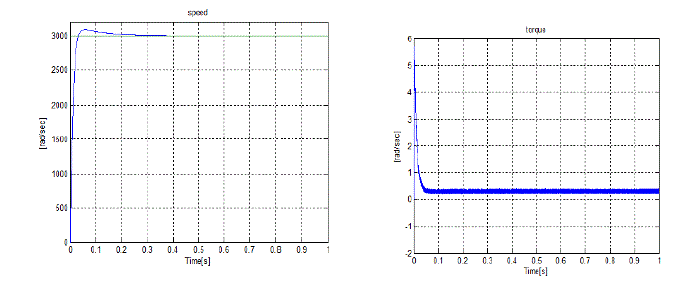
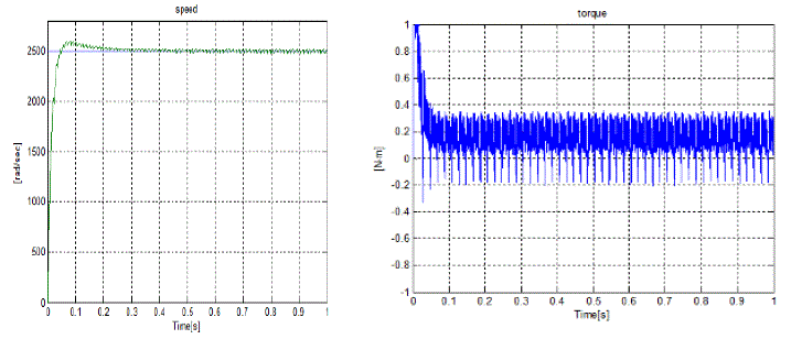
| From the above simulation results although there is a ripple in the speed waveform it tracks the set value after
0.25sec. |
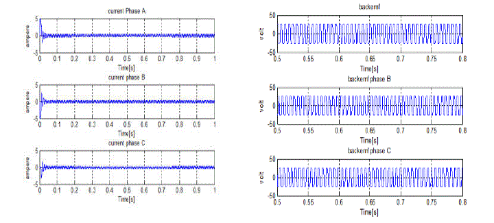
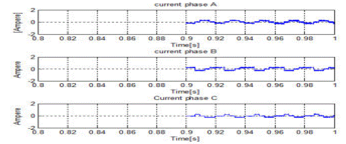
| The torque ripple also attain a steady value after 0.09 sec. Due the open phase the current waveform is disturbed
slightlybut |
| it can effectively run the motor to continue the operation |
IV. CONCLUSION |
| A simple technique for fault detection and identification ofBLDC motors is proposed.The fault tolerant control
model has simulated with effectively reduced torque ripple level. By adjusting the PI controller the peak overshoot of
the system is reduced effectively. |
Tables at a glance |
 |
| Table 1 |
|
| |
Figures at a glance |
 |
 |
 |
 |
| Figure 1 |
Figure 2 |
Figure 3 |
Figure 4 |
 |
 |
 |
| Figure 5 |
Figure 6 |
Figure 7 |
|
| |
References |
- F. Aghili, “Fault-tolerant ripple-free torque control of brushless motors,” Presented at the IEEE Int. Conf.Mechatron. Autom. (ICMA), Xian, China, Aug. 2010, pp. 947–954.
- BaloghTibor, Viliam Fed, " Modeling and Simulation of the BLDC Motor in MATLAB GUI,” J. Basic. Appl. Sci. Res., 2(12)12066-12077, 2012.
- Byoung-Gun Park, Kui-Jun Lee, Rae-Young Kim, “ Simple Fault Diagnosis Based on Operating Characteristic of Brushless Direct-Current Motor Drives,” IEEE Transactions on Industrial Electronics, vol. 58, no. 5, may 2011 and Magnetism, 3rd ed., vol. 2. Oxford: Clarendon, 1892, pp.68-73.
- T. Gopalarathnam, H. A. Toliyat, and J. C. Moreira, “Multi-phase fault tolerant brushless DC motor drives,” in Proc. IEEE Ind. Appl. Conf., Rome, Italy, Aug. 2000, pp. 1683–1688.
- Dong-SeokHyun,B.G.Park, K.J.Lee, Rae-Young Kim, “ Low-Cost Fault Diagnosis Algorithm for Switch Open-Damage in BLDC Motor Drives,” Journal of Power Electronics, Vol. 10, No. 6, November 2010.
- R. Spee and A. K. Wallace, "Remedial strategies for brushless DC The aim of this preliminary paper is to evaluate the basic drive failures ", IEEE Transactions on Industry Applications, common faults that could occur within a BLDC drive system 26(2):259-266, 1990.
- Byoung-Kuk Lee, Tae-Hyung Kim and M. Ehasani, "On the Feasibility of Four-Switch Three-Phase BLDC Motor Drives for fault Low Cost Commercial Applications: Topology and Control," IEEE Trans. Power Electron., vol. 18, no. 1, pp. 164-172, Jan. 2003.
|