This paper evaluates the performance of a grid connected hybrid system. Renewable energy is currently widely used. One of these resources is solar energy. The hybrid system composed of a Photovoltaic (PV) array and a Proton exchange membrane fuel cell (PEMFC) is considered. The PV array acquaints with an improved maximum power point tracking (MPPT) technique to a grid connected hybrid system to continuously deliver the highest power to the load when variations in irradiation and temperature occur. The disadvantage of PV energy is that the PV output power depends on weather conditions and cell temperature, making it an uncontrollable source. Furthermore, it is not available during the night. In order to overcome these inherent drawbacks, alternative sources, such as PEMFC(Proton Exchange membrane fuel cell) is installed in the hybrid system. By changing the FC output power, the hybrid source output becomes controllable. The hybrid source has two control modes: 1) unit-power control (UPC) mode and 2) feeder-flow control (FFC)mode. The coordination of two control modes, the coordination of the PV array and the PEMFC in the hybrid system is presented in this paper
Keywords |
| Hybrid system, fuel cell, micro grid, photovoltaic, power management. |
INTRODUCTION |
| . Hybrid power systems combine two or more energy conversion devices, or two or more fuels for the same device, that
when integrated, overcome limitations inherent in either [1]. Hybrid systems can address limitations in terms of fuel
flexibility, efficiency, reliability, emissions and / or economics. Hybrid systems can be designed to maximize the use of
renewables, resulting in a system with lower emissions than traditional fossil-fuel technologies [2]. Hybrid systems can
be designed to achieve desired attributes at the lowest acceptable cost, which is the key to market acceptance. Now a
day‘s most popular renewable energy resources are solar, wind and fuel cells [3]. The photovoltaic (PV) array normally
uses a maximum power point tracking (MPPT) technique to continuously deliver the highest power to the load when
there are variations in irradiation and temperature. The disadvantage of PV energy is that the PV output power depends
on weather conditions and cell temperature, making it an uncontrollable source. Furthermore, it is not available during
the night [5]. |
| In this paper, in order to overcome these inherent drawbacks, alternative sources, such as PEMFC, should be installed
in the hybrid system. By changing the FC output power, the hybrid source output becomes controllable.
However, PEMFC, in its turn, works only at a high efficiency within a specific power range ( PFClow / PFCup) [1],
[2]. The hybrid system can either be connected to the main grid or work autonomously with respect to the gridconnected
mode or islanded mode, respectively. In the grid-connected mode, the hybrid source is connected to the main
grid at the point of common coupling (PCC) to deliver power to the load. When load demand changes, the power
supplied by the main grid and hybrid system must be properly changed. The power delivered from the main grid and
PV array as well as PEMFC must be coordinated to meet load demand. The hybrid source has two control modes: 1)
unit-power control (UPC) mode 2) Feeder flow control (FFC) mode. This operating strategy will minimize the number
of operating mode changes, improve performance of the system operation, and enhance system stability. |
II.SYSTEM DESCRIPTION |
| The system consists of a PV-FC hybrid source with the main grid connecting to loads at the PCC as shown in Fig. 1.
The photovoltaic [3],[4] and the PEMFC [5],[6] are modeled as nonlinear voltage sources. These sources are connected to dc–dc converters which are coupled at the dc side of a dc/ac inverter. The dc/dc connected to the PV array works as
an MPPT controller. Many MPPT algorithms have been proposed in the literature, such as incremental conductance
(INC), constant voltage (CV), and perturbation and observation (P&O). The P&O method has been widely used
because of its simple feedback structure and fewer measured parameters [7]. As PV voltage and current are determined,
the power is calculated. At the maximum power point, the derivative (dP/dV) is equal to zero. The maximum power
point can be achieved by changing the reference voltage by the amount of ΔVref. |
| A. PV Array Model |
| PV modules still have relatively low conversion efficiency; therefore, controlling maximum power point tracking
(MPPT) for the solar array is essential in a PV system. The amount of power generated by a PV depends on the
operating voltage of the array. A PV‘s maximum power point (MPP) varies with solar insulation and temperature. It‘s
V-I and V-P characteristic curves specify a unique operating point at which maximum possible power is delivered. At
the MPP, the PV operates at its highest efficiency. |
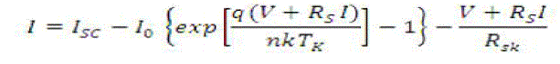 (1) (1) |
| Where V and I represent the output voltage and current of the PV, respectively; Rs and Rsh are the series and shunt
resistance of the cell; q is the electronic charge; Isc is the light-generated current; Io is the reverse saturation current; n is
a dimensionless factor; k is the Boltzmann constant, and Tk is the temperature in 0K. Equation (1) was used in computer
simulations to obtain the output characteristics of a solar cell, as shown in Figure 3. This curve clearly shows that the
output characteristics of a solar cell are non-linear and are crucially influenced by solar radiation, temperature and load
condition. Each curve has a MPP, at which the solar array operates most efficiently. |
| B. PEMFC Model |
| Among various types of fuel cells, such as, Alkaline (AFC), Phosphoric Acid (PAFC), Molten Carbonate (MCFC),
Solid Oxide (SOFC), Proton Exchange Membrane fuel cells (PEMFC) are the most promising.
The internal potential ECELL |
 (2) (2) |
| Here * refers the effective value. |
| Activation loss, ohmic resistance voltage drop, and concentration over potential are voltage drops across the fuel cell,
as shown in Fig. 4. |
 (3) (3) |
| Therefore the output voltage of the fuel-cell stack can be obtained as |
 (4) (4) |
| Here ‗ E‘ is the eversible potential of each cell (in volts) |
| To calculate the fuel-cell output voltage, the following estimations are used: |
| 1) Activation Voltage Drop: Tafel equation, given below, is used to calculate the activation voltage drop in a fuel
cell |
 (5) (5) |
| 2) Ohmic Voltage Drop:. The overall ohmic voltage drop can be expressed as |
 (6) (6) |
| 3) Concentration Voltage Drop: The concentration over potential in the fuel cell is defined as [8] |
 (7) (7) |
| Where CS is the surface concentration and CB is the bulk concentration |
 (8) (8) |
| The equivalent resistance for the concentration loss is |
 (9) (9) |
| C. MPPT Control |
| Many MPPT algorithms have been proposed in the literature [3][4], such as incremental conductance (INC),
constant voltage (CV), and perturbation and observation (P&O). |
| The two algorithms often used to achieve maximum power point tracking are the P&O and INC methods. The INC
method offers good performance under rapidly changing atmospheric conditions. However, four sensors are required to
perform the computations. If the sensors require more conversion time, then the MPPT process will take longer to track
the maximum power point. During tracking time, the PV output is less than its maximum power. This means that,
longer the conversion time is, larger the power loss [3],[4]. On the contrary, if the execution speed of the P&O method
increases, then the system loss will decrease. Moreover, this method only requires two sensors, which results in a
reduction of hardware requirements and cost. Therefore, the P&O method is used to control the MPPT [5][6] process.
The power-feedback control is used to achieve maximum power. As PV voltage and current are determined, the power
is calculated. The maximum power point can be achieved by changing the reference voltage by the amount of ΔVref . In
order to implement the MPPT algorithm, a buck-boost dc/dc converter is used as depicted in Fig. 5. The parameters L
and C in the buck-boost converter must satisfy the following conditions [9]. |
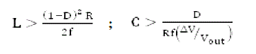 (10) (10) |
| The buck–boost converter is a type of DC-to-DC converter that has an output voltage magnitude that is either greater
than or less than the input voltage magnitude. It is a switched-mode power supply with a similar circuit topology to the
boost converter and the buck converter. |
III. CONTROL AND OPERATING STRATEGY OF THE HYBRID SYSTEM |
| The control modes in the micro grid include UPC, FFC and mixed control mode[7]. In the UPC mode, the DGs (the
hybrid source in this system) regulate the voltage magnitude at the connection point and the power that source is
injecting. In this mode if a load increases anywhere in the micro grid, the extra power comes from the grid, since the
hybrid source regulates to a constant power.Fig6 shows the control algorithm diagram for determining the reference
power automatically. |
| A. Overall operating strategy for the grid connected hybrid system |
| The boundary between Area I and Area II Pload1 is |
 (11) (11) |
| When the mode changes to FFC, the feeder flow reference must be determined. Accordingly, when the feeder flow
reference is set at Pfeeder
max then we have |
 (12) (12) |
| The limit that load shedding will be reached is |
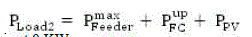 (13) (13) |
| Pload2 is minimal when PV output is at 0 KW |
 |
| Thus, the load can be higher and the largest load is |
 (14) (14) |
| If FC power and load demand satisfy the above equation load shedding will never occur corresponding to the FC
installed power, the width of Area II is calculated as follows: |
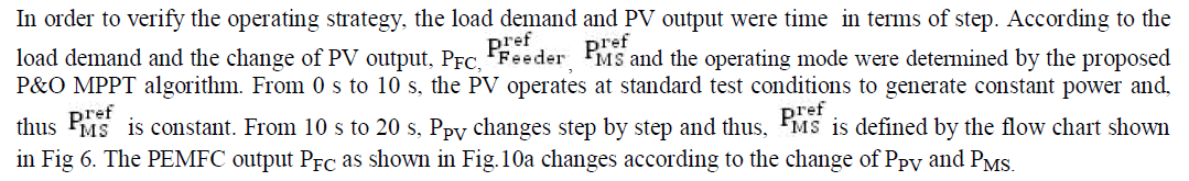
IV.SIMULATION RESULTS |
| A. Simulation Results in the Case Without Hysteresis |
| A simulation was carried out by using the system model shown in Fig. 8. To verify the operating strategies the system
parameters are shown in Table 1. |
 |
 |
V.CONCLUSION |
| This paper has presented an available method to operate a hybrid grid-connected system. The hybrid system,
composed of a PV array and PEMFC, was considered. The operating strategy of the system is based on the UPC mode
and FFC mode. The purposes of the proposed operating strategy presented in this paper are to determine the control
mode, to minimize the number of mode changes, to operate PV at the maximum power point, and to operate the FC
output in its high-efficiency performance band. |
Tables at a glance |
 |
| Table 1 |
|
| |
Figures at a glance |
 |
 |
 |
 |
 |
| Figure 1 |
Figure 2 |
Figure 3 |
Figure 4 |
Figure 5 |
 |
 |
 |
 |
 |
| Figure 6 |
Figure 7 |
Figure 8 |
Figure 9 |
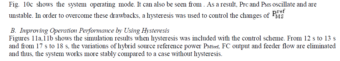
Figure 10a |
 |
 |
 |
 |
| Figure 10b |
Figure 10c |
Figure 11a |
Figure 11b |
|
| |
References |
- T. Bocklisch, W. Schufft, and S. Bocklisch, “Predictive and optimizing energy management of photovoltaic fuel cell hybrid systems withshort time energy storage,” in Proc. 4th Eur. Conf. PV-Hybrid and Mini-Grid, 2008, pp. 8–15.
- J. Larmine and A. Dicks, Fuel Cell Systems Explained. New York: Wiley, 2003.
- W. Xiao, W. Dunford, and A. Capel, “A novel modeling method for photovoltaic cells,” in Proc. IEEE 35th Annu. PowerElectronics Spe-cialists Conf., Jun. 2004, vol. 3, pp. 1950–1956.
- D. Sera, R. Teodorescu, and P. Rodriguez, “PV panel model based on datasheet values,” in Proc. IEEE Int. Symp. IndustrialElectronics, Jun. 4–7, 2007, pp. 2392–2396.
- C. Wang, M. H. Nehrir, and S. R. Shaw, “Dynamic models and model validation for PEM fuel cells using electrical circuits,” IEEE Trans. Energy Convers., vol. 20, no. 2, pp. 442–451, Jun. 2005.
- C. Hua and C. Shen, “Comparative study of peak power tracking tech-niques for solar storage system,” in Proc. 13th Annu. Applied Power Electronics Conf. Expo., Feb. 1998, vol. 2, pp. 679–685.
- A. Hajizadeh and M. A. Golkar, “Power flow control of grid-connected fuel cell distributed generation systems,” J. Elect. Eng. Technol., vol. 3, no. 2, pp. 143–151, 2008.
- C. Hua and J. R. Lin, “DSP-based controller application in battery storage of photovoltaic system,” in Proc.22nd IEEE Int. Conf. Indus-trial Electronics, Control, and Instrumentation, Aug. 5–10, 1996, vol. 3, pp. 1750–1810.
- C. Hua, J. Lin, and C. Shen, “Implementation of a DSP-controlled pho-tovoltaic system with peak power tracking,” IEEE Trans. Ind. Electron., vol. 45, no. 1, pp. 99–107, Feb. 1998.
- E. Koutroulism and K. Kaalitzakis, “Development of a microcon-troller-based, photovoltaic maximum power point tracking control system,” IEEE Trans. Power Electron., vol. 16, no. 1, pp. 46–54, Jan. 2001.
|