Plug in Hybrid Electric Vehicles (PHEVs) charging and discharging, renewable energy resource generation and utilization is most important in future power system control. Proper integration of these energy sources gives solution to the challenges. In this paper Mixed Integer Linear Programming (MILP) was proposed for plug in Hybrid Electric Vehicles charging and discharging in a charging station. Charging station consists of Photo Voltaic (PV) system with practical constraints, power balance constraints, battery charging and discharging constraints are considered. The results proposed that the proposed algorithm minimize the charging cost of PHEVs and optimal power flow for the grid connected PHEVs systems. Likewise, PHEVs owners could yield more profit by discharging their vehicles to the grid in addition to having preferred charge in the departure time.
Keywords |
| Mixed Integer Linear Programming, Plug in Hybrid Electric Vehicles, Charging Park, Voltage
Stability. |
INTRODUCTION |
| The importance of energy savings is increasing and governments are encouraging the use of renewable energy. A clear
correlation can be observed between vehicle density (cars per 1000 inhabitants) and a country‘s GDP (Gross Domestic
Product); this suggests that as densely populated countries such as China, India, and Brazil achieve higher economic
status, it can be expected that the demand for personal transportation will increase accordingly. Today, this demand can
be directly translated into increased demand for petroleum, a fact that is hardly compatible with current data on oil
production. Plug-In Electric Vehicles are receiving a great deal of interest in the United States due to their energy
efficiency, convenient and low-cost recharging capabilities and reduced use of petroleum. PHEVs are an important of
an electric power system in the upcoming days. |
| PHEVs give the solution to the fossil fuel shortage and air pollution problems [1].The emission reduction is achieved
by using the PHEVs with combination of renewable energy resources. Beyond these advantages, the power system may
face significant challenges due to the huge electricity demand of these loads [2-4]. PHEVs use battery as an energy
storage system by using this battery PHEVs supply the power to the electric drive motor. Whenever PHEVs connected
to charging station it will be operated in two modes such as Vehicle to Grid (V2G) mode and Grid to Vehicle (G2V)
mode [5-6]. In V2G mode the state of charge of battery can go up or down, depends on the power demand. PHEVs
owner get profit by using V2G capabilities. The design of PHEVs energy storage is mainly for transportation sector. So
it provides sufficient energy to drive the vehicle. In order to maximize the customer satisfaction and minimize the grid
disturbance, PHEVs charging station gives the solution for the energy management challenges [7-8].c |
| An estimation of distribution algorithm to schedule the large number of PHEVs charging in a charging station has been
proposed. The method optimizes the energy allocation to the PHEVs in the real time while considering various
constraints. This paper has only proposed the charging method of PHEVs and the V2G option does not consider
[9].The authors in [10] proposed simulated annealing approach and heuristic technical validation of the obtained
solutions to solve the energy resources scheduling. In this paper, charging station with PV system on the roof,
bidirectional utility grid for charging and discharging of PHEVs are presented. The grid connection is to satisfy the
demand. Excess PV output is sent to the grid during peak hours. An energy management system with PV based charging station is proposed here in which the PV generation uncertainty and V2G capability of PHEVs are considered
[11]. Moreover, the proposed model considers system constraints and customer's preferences. The contributions of the
proposed method are highlighted as follows: |
| The rest of the paper is organized as follows: in Section 2, the proposed system components are introduced. Section3
presents the problem formulation; including the resources and PHEVs constraints. Analysis of the results is shown in
Section4. Finally, conclusion is presented in Section5. |
COMPONENTS OF PROPOSED SYSTEM |
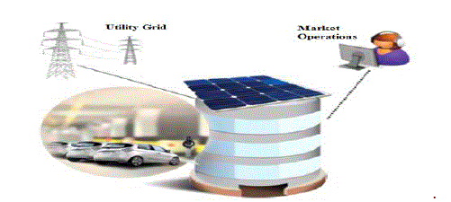
| This section deals with the architecture of the proposed system which includes the multiple PV panel on the roof of the
charging station and PHEVs are shown in fig 1. In addition there is a point of connection to the utility grid to enable the
electricity trading with utility grid. In this paper the charging station plays the important role for the Energy
Management System in (EMS) PHEVs. PHEVs are parked in the charging station can deliver the power to the grid or
absorb the power from it according to the State of Charge (SOC) presents on their battery. The PHEV‘s owner not only
uses the space for parking the vehicle and also benefit from V2G capabilities. |
A. Charging Station1 |
| The charging station is compared to conventional one present‘s new facility to PHEV‘s owners and the utility grid.
This energy management system automatically receives and sends data to vehicles and makes a smart decision
regarding the scheduling of charging and discharging of the PHEVs. The PHEVs owner can submit their desired
parameters of charging as previous day by using smart phone application. The charging station receives parameters
from each PHEVs owner, such as arrival time, duration of presence in the charging station approximately and the
minimum required state of charge at the departure time. These parameters are considered as input data. Charging
station first receives the day-ahead electricity prices, PHEVs owners‘ preferences and the forecasting data of solar
radiations as the input data. Then PV power and PHEVs charge/discharge program is determined by charging station
control itself. Finally the result of optimum charge/discharge scheduling is sent to each PHEVs owner. |
B. Bi-Directional Converter |
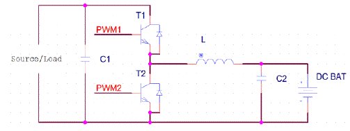
| The purpose of the Bi-Directional converter in the PHEVs charger system is to interface the battery with the system
enabling it to charge and discharge when needed. In a buck mode, this converter will lower the output voltage going to
the input of the battery to a safe level enabling the battery to safely charge to a full level. The Bi-Directional converter
is shown in fig 2.If the system is not charging; the converter can be switch into its next mode. In this mode, the battery
will discharge and increase the voltage to drive the load. |
| The bi-directional function of this circuit is given by two switching transistors, T1 and T2. These transistors will
receive control signals from the controller directing the flow of current. When the current through the inductor is
positive means it will act as buck converter. When the current through the inductor is negative means it will act as
boost converter. |
C. Photovoltaic Panels |
| Solar power varies in the day-time as a result of the changing position of the sun and the motion of clouds. Such
variability and uncertainty should be carefully considered in the proposed energy management system design. In recent
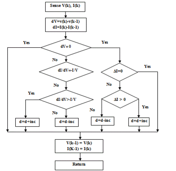
years, a large number of techniques have been proposed for tracking the Maximum Power Point (MPP). Maximum
Power Point Tracking (MPPT) is used in PV systems to maximize the photovoltaic array output power. PV array output
power is used to directly control the DC to DC converter, thus reducing the difficulty of the system. Incremental
conductance of MPPT flow chart is shown in fig 3. The method is based on use of an Incremental conductance of the
PV to determine an optimum operating current for the maximum output power. In incremental conductance method the
array terminal voltage is always adjusted according to the MPP voltage it is based on the incremental and instantaneous
conductance of the PV module. The MPPT regulates the PWM control signal of the Dc to DC boost converter until the
condition: (∂I/∂V) + (I/V) = 0 is satisfied. |
D. Li-Ion Battery |
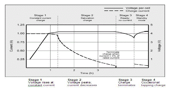
| One of the primary goals is to optimally charge a high power battery. A single Lithium cell break-down of the charging
stages is shown in fig 4. The selected battery consists of 400 Cell for charging purpose (288V). Lithium-Ion battery
with a total rated capacity of 13.9 [Ah] is used for charging the PHEVs. Each lithium-Ion cells has a voltage of 4.2V at
maximum capacity. Maintaining maximum state of charge on a Li-Ion battery puts a large amount of stress on the cells,
and shortens the overall lifespan of the battery. |
IMPLEMENTATION OF MIXED INTEGER LINEAR PROGRAMMING METHOD TO SOLVE THE
EMS PROBLEM |
 |
A. Constraints |
| The main objective function is charging cost minimization with respect to various constraints [12].That constrains are
explained as follows: |
a) Power Balance Constraint: |
 |
 |
b) Remaining Battery Power for each PHEVs: |
| The stored energy in the battery is considered together with the energy remaining from the previous period and the
charge or discharge in the period‗t‘. |
 |
 |
 |
| To solve the EMS problem the MILP method has two specific advantages compared to other optimization methods. In
the proposed model, the MILP optimization guarantees to find the globally optimum solution [13]. Also, The MILP
optimization finds the optimum solution in lower runtime [14, 15]. Moreover, the proposed model is a day-ahead
energy and reserve scheduling. The computation time is also an important aspect of the applicability of the proposed
method. For a real size charging parks with large number of EVs the MILP shows its benefits in a light execution time. |
RESULTS AND DISCUSSION |
| The simulink model for the proposed MILP method were developed using MATLAB 7.10 software package and the
system configuration is Intel Core i5-2410M Processor with 2.90 GHz speed and 4 GB RAM. In proposed work two
energy sources are considered. Computational results of EMS problem attained by the proposed MILP method for the
two energy sources analyzed. |
A. Waveform of Utility Grid |
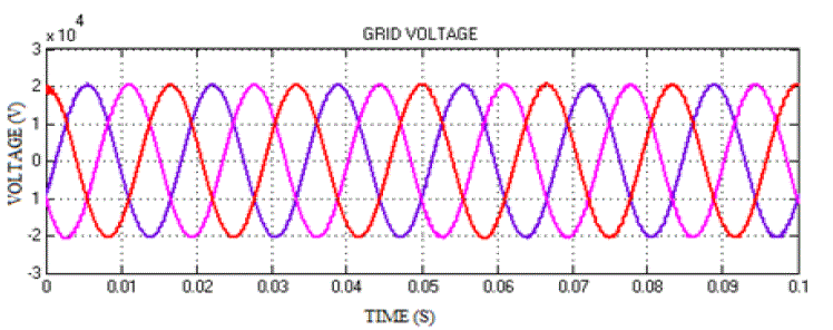
| Utility grid connects with the charging station through the DC bus. The output voltage waveform of utility grid is
shown in fig. 5. It produces 20 kW output voltages from generating station. Output is transferred to DC bus through the
bi directional converter. Utility grid is synchronized by using VSC control |
B. Waveform of DC Bus |
| Photo voltaic system‘s maximum power point is continuously tracked and integrated into the dc-bus linking the
PHEVs‘ batteries to the main grid. The output voltage waveform of DC bus is shown in fig. 6. DC bus is connected
with utility grid and charging station. DC bus voltage is maintained at 480v. |
C. V2G and G2V |
| Power output of the various V2G and G2V conditions is shown in Table I. the main objective of the proposed method
is to minimize the charging cost of plug in hybrid electric vehicles. The various algorithm techniques and its charging
cost of PHEVs are shown in Table II. |
CONCLUSION |
| The proposed method provides the optimal power flow and charging cost minimization of plug in hybrid electric
vehicles. It improves the performance of V2G and G2V functionalities by using renewable sources. The photovoltaic
and Fuel cell model was designed using MATLAB. The excess energy which is produced from photovoltaic and fuel
cell power is transferred to the electrical network. PHEVs system is designed and charging cost is minimized by using
MILP method. The proposed method satisfies the optimal power flow in the PHEVs system and also improves the
system efficiency and minimizes the losses. The excess energy from renewable energy resources can also be sent to the
utility grid and also satisfies the power demand. |
Tables at a glance |
 |
 |
| Table 1 |
Table 2 |
|
Figures at a glance |
 |
 |
 |
| Figure 1 |
Figure 2 |
Figure 3 |
 |
 |
 |
| Figure 4 |
Figure 5 |
Figure 6 |
|
References |
- H.A.Sher, K.E.Addoweesh, M.E.Webber, ―Power storage options for hybrid electric vehicles—a survey,‖ J. Renew. Sustain. Energy, vol. 4, no. 5, pp. 1-11, 2012.
- Q.Zhang, N.K.Ishihara, C.B.Mclellan, T.Tezuka, ―Scenario analysis on electricity supply and demand in Japan,‖ Sustain.Energy, vol. 38, no. 1, pp. 376-385, 2012.
- M. Pantos, ―Stochastic optimal charging of electric drive vehicles with renewable energy,‖ Sustain. Energy, vol. 36, no. 11, pp. 6567–6576, 2012.
- B. Soares, M.C.Borba, A.Szklo, R.Schaeffer, ―Plug in hybrid electric vehicles as a way to maximize the integration of variable renewable energy in power system: the case of wind generation in north eastern Brazil,‖ Sustain Energy, vol. 37, no. 1, pp.469-481, 2012.
- Z. Ma, D. Callaway, I. Hiskens, ―Decentralized charging control for large populations of plug-in electric vehicles: application of the nash certainty equivalence principle,‖ IEEE International Conference on Control Applications (CCA), Yokohama, Japan, 2010.
- S.Rezaee,E.Farjah, B.Khorramdel, ―Probabilistic analysis of plug-in electric vehicles impact on electrical grid through homes and parking lots,‖ IEEETrans.Sustain.Energy, vol. 4, no. 4, pp. 1024–1033, 2013.
- M. Honarmand, A.Zakariazadeh, S.Jadid, ―Optimal scheduling of electric vehicles in an intelligent parking lot considering vehicle-to-grid concept and battery condition,‖ Renewable Energy, vol. 65, pp. 572–579, 2014.
- S. Shahidinejad, S.Filizadeh , E.Bibeau, ―Profile of charging load on the grid due to plug-in vehicles,‖ IEEE Trans. Smart Grid, vol. 3, no. 1, pp. 135-141, 2012.
- W. Su, M.Y.Chow, ―Performance evaluation of an EDA-based large-scale plug-in hybrid electric vehicle charging algorithm,‖ IEEE Trans. Smart Grid, vol. 3, no. 1, pp. 308–315, 2012.
- T. Sousa, H.Morais, Z.Vale ,P.Faria, J.Soares, ―Intelligent energy resource management considering vehicle-to- Grid: a simulated annealing approach,‖ IEEE Trans. Smart Grid, vol. 3, no. 1, pp. 535–542, 2012.
- Ahmed Mohamed, VahidSalehi, Osama A. Mohammed, ―Real-Time Energy Management Algorithm for Plug-In Hybrid Electric Vehicle Charging Parks Involving Sustainable Energy,‖ IEEE Trans. Sustainable Energy, vol. 5, no. 2, pp. 577-586. Apr 2014.
- MasoudHonarmanda, AlirezaZakariazadeha, ShahramJadid, ―Self-scheduling of electric vehicles in an intelligent parking lot using stochastic optimization,‖ sciencedirect, Journal of the Franklin Institute,Jan 2014.
- T.Koch, T.Achterberg, E.Andersen, O.Bastert, T.Berthold, R.E.Bixby, etal., ―MIPLIB2010‖,Math.Program. Comput., no. 3, pp.103–163, March 2011.
- A. Zakaria zadeh,S.Jadid,P.Siano,‖Economic-environmental energy and reserve scheduling of smart distribution systems: a multi objective mathematical programming approach,‖ Energy Convers. Mag, vol. 78, pp. 151–164. April 2014.
- H.Falsafi, A.Zakariazadeh, S.Jadid, ―The role of demand response in single and multi-objective wind-thermal generation scheduling: astochastic programming,‖ Energy Convers.Mag, vol. 64, pp. 853–867, June 2014
|