Recently, there has been great interest in the integration of distributed generation units at the distribution level. The foreseeable large use of DG in the future requires the distribution system engineers to properly take into account its impact in the system planning. When considering DG impact the attention should be paid in the siting and sizing of DG units. This paper proposes the use of analytical expressions for finding the optimal size and site of DG in distribution systems.
Keywords |
| DG, sizing, siting, Exact Loss Formula, BIBC and BVBC. |
INTRODUCTION |
| Distributed generation unlike centralized electrical generation aims to generate electrical energy on small scale as near as
possible to load centers, which provide an incremental capacity to power system. In the deregulated power market, concerns about
the environment as well as economic issues have led increased interest in distributed generations. The emergence of new
technological alternatives (photovoltaic systems, wind power, cogeneration, etc.) allows generating part of the required energy
closer to the point of use, improving quality levels and minimizing the investments costs associated with of transmission and
distribution systems. |
| With electricity market undergoing tremendous transformation, more price instability in the market, ageing infrastructure and
changing regulatory environments are demanding users and electric utilities to exploit benefits of DG [1, 2]. DGs are expected to
play key role in future markets because of their economic feasibility and based on the study of Electric Power Research Institute
(EPRI) and Natural Gas Foundation, 30% of power generation share will be of DG [3,4]. The decreasing availability of natural
resources and the increasing consciousness of environmental protection have rapidly increased the share of DG in the electricity
supply. Many definitions of DG have appeared in the literature based on their size, technologies, location, power delivery area and
operational constraints with their economical and operational benefits [5–7]. |
| Distributed generation (DG) represents a change in the standard of electrical energy generation. The penetration of DG in the
distribution system changes the power flow in the traditional network of electric power distribution system from unidirectional to
multidirectional system. With increased use of distributed generations in distribution network has changed the nature of network
from passive to active. One of the main obstacles for high DG penetration in the distribution feeder is the voltage rise effect which
can be rectified by the selection of appropriate size and number of DGs [8]. Distribution system performance can be improved with
the effective integration of DG. Under such circumstances, the DG offers a feasible alternative to traditional sources of the electric
power. |
| The foreseeable large use of DG in the future requires the distribution system engineers to properly take into account its impact
in the system planning. When considering DG impact the attention should be paid in the siting and sizing of DG units. The
operation of DG can provide benefits to distribution networks such as reduction of power losses and/or deferment of investments for
network enforcing, etc. only if it is allocated properly otherwise it can cause degradation of power quality, increase losses, reliability, and control etc. For benefits and foreseeable large use of DG in future attention on the sizing and siting of DGs has been
paid by many researchers [9-19]. |
| Celli et al. [9] proposed an algorithm to determine location and size of distributed generators by minimizing different functions
related to cost of energy losses, cost of service interruptions, cost of network upgrading and cost of energy purchased. Devi and
Subramanyam [10] used fuzzy logic for DG placement and calculations at given power factor. Dasan and Devi [11] used fuzzy
adaptation of evolutionary programming to find size of DGs. Wallance and Harrison [12] presented the optimal power flow based
technique to determine the maximum capacity of generation that can be accommodated in a network. Dent [13] used optimal power
flow based method incorporating voltage step constraints for determining the capacity of network to accommodate DG. A hybrid
method employing genetic algorithms and optimal power flow is presented by Harrison et al. [14] to find sites in a distribution
network for connecting a pre defined number of DGs. A multi-objective performance index-based determination of size and location
of DG in distribution systems with different load models was presented by Singh et al. [15] and implemented using GA. A
methodology based on GA was presented by Singh and Goswami [16] to accommodate DG in distribution network by maximization
of profit, reduction of losses and improvement in voltage regulation. Implementation of Distributed Generation was proposed by
Khan and Choudhry [17] to find optimal size and location of DG in presence of non-uniformly distributed loads. The size and power
factor for DG were found by using analytical expressions in [18-19] to minimize losses. |
| Electrical energy is continuously lost due to resistance in power system networks, and distribution system loss accounts for
more compared to transmission system. Moreover, distribution systems are well known for a higher R/X ratio compared to
transmission systems and significant voltage drops can result in substantial power and energy losses along distribution feeders. As a
result, loss reduction in distribution systems is one of the greatest challenges to many utilities around the world. Earlier
reconfiguration and capacitors placement are two major methods for loss reduction in distribution systems but nowadays DG can be
added in system to reduce losses. |
| The paper is organized as follows: Section II discusses about techniques of loss reduction in distribution systems. Section III
includes the methodology to find the optimum size and site of DG for loss reduction. In Section IV used test system is discussed.
Section V discusses the performance of proposed technique and at last section VI concludes the paper and followed by the
references. |
II. LOSS REDUCTION TECHNIQUES |
| There have been many studies on the reconfiguration of distribution systems for loss reduction. A switch exchange algorithm
was proposed in [20]. In [21], an approximate power-flow technique was developed for analyzing loss reduction from network
reconfiguration. In [22], Fan et al. formulated the reconfiguration problem as a linear programming problem and applied a singleloop
optimization method to solve network reconfiguration. Other techniques such as the simulated annealing (SA), genetic
algorithm (GA), improved Tabu Search (TS), and ant colony search (ACS) algorithm have been used for the purpose of network
reconfiguration for reducing losses. For optimal capacitor placement a well known “Golden Rule,” or “2/3 rule” for loss reduction,
is presented in [23]. This method would yield good solutions in system where the loads are uniformly distributed. In distribution
systems, DG can deliver a portion of real and/or reactive power so that the feeder current is reduced and voltage profile can be
improved with reduction in losses. However, studies indicate that poor selection of location and size would lead to higher losses
than the losses without DGs [18], [23]. A technique for DG placement using “2/3 rule” has been presented in [23]. Although the 2/3
rule is simple and easy to apply, this technique may not be effective in distribution with not uniformly distributed loads. Besides, if a
DG is capable of delivering real and reactive power, applying the method that was developed for capacitor placement may not work.
In [24], an analytical approach has been presented to identify appropriate location to place single DG in radial as well as loop
systems to minimize losses. But, in this approach, optimal sizing is not considered. |
| In this paper, an analytical expression to calculate optimum size and site for DG placement are proposed. The methodology is
computationally less demanding. The DG is considered to be located in the primary distribution system and the objective of DG
placement is to reduce the losses. The proposed methodology is suitable for allocation of single DG in a given distribution network. |
III. PROPOSED METHODOLOGY |
| a. Exact Loss Formula |
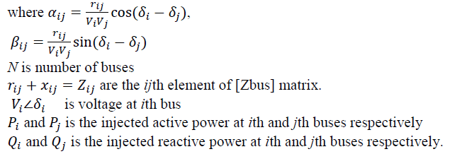
| The real power loss in a system is given (1) which is known as “Exact loss” formula. |
 (1) (1) |
 |
| b. Optimal Sizing of DG |
| The total power loss against injected power is a parabolic function and at minimum losses the rate of change of losses with respect
to injected power becomes zero [18]. |
 (2) (2) |
| It follows that |
 (3) (3) |
| where, Pi is the real power injection at node i, which is the difference between real power generation and the real power demand at
that node: |
 (4) (4) |
| where, PDGi is the real power injection from DG placed at node i, and PDi is the load demand at node i. By combining the above, we
get |
 (5) (5) |
| The above equation gives the optimum size of DG for each bus i, for the loss to be minimum. Any size of DG other than PDGi placed
at bus i, will lead to higher loss. |
| c. Optimal Location to minimize Loss |
| After finding optimal size of DG at each bus, next step is to find the optimum location of DG, which will give the lowest possible
total losses. The bus having least power loss will be optimal location for the placement of DG [18]. |
| d. Computational Algorithm |
| Step 1: Run the base case load flow |
| Step 2: Find the optimum size of DG for each bus using Eq. (5). |
| Step 3: Compute loss using Eq. (1) for each bus by placing DG of optimum size obtained in step 2 for that bus. Add the injection from DG for that bus and use base case values for all other variables. |
| Step 4: Locate the bus at which the loss is minimum after DG placement. This is the optimum location for DG. |
| Step 5: Run load flow with DG to get the final result. |
IV. TEST SYSTEM |
| The proposed methodology is tested on a test system i.e. 33-bus radial distribution system with total load of 3.72 MW
and 2.3 MVAR. A computer program has been written in MATLAB 7.10 to calculate the optimum sizes of DG at
various buses and approximate total losses with DG at different locations to identify the best location. An algorithm
based on bus-injection to branch-current (BIBC) and branch-current to bus voltage (BCBV) matrices is used to solve
the load flow problem for radial distribution networks. |
V. RESULTS AND DISCUSSIONS |
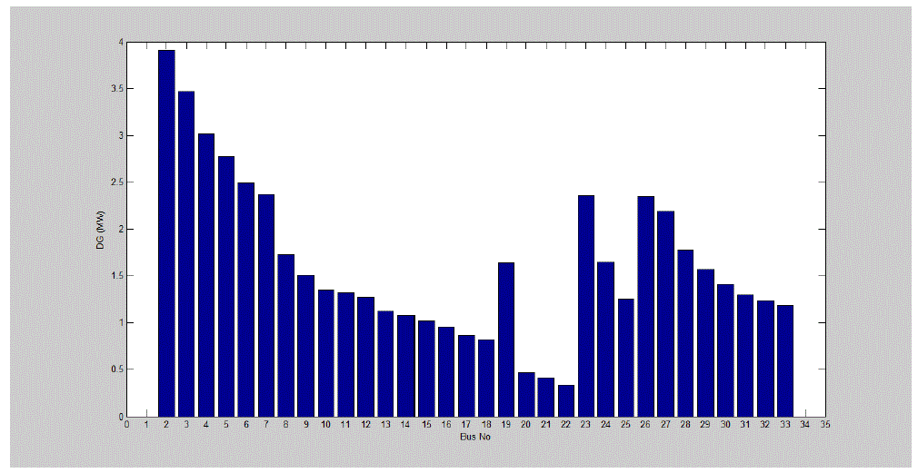
| Based on the analytical expressions, optimum sizes of DGs are calculated using (5) at various nodes for the test system. Fig. 1
shows optimum sizes of DG at various buses for 33 bus distribution test systems. In this test System the range of optimum sizes of DG is from 0.3 MW to 3.9 MW. Now, it is important to find the optimal location of DG for which total power loss will be
minimum. This is done with help of calculating approximate loss using (1). For 33-bus Radial Distribution test System the optimal
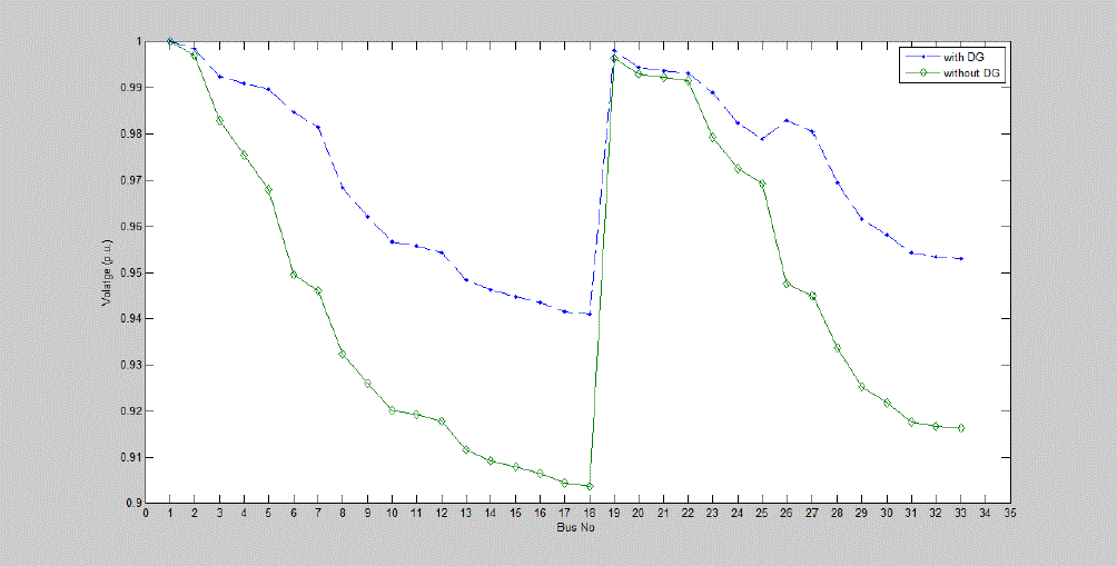
location is bus 6 where total power loss is 111.12 kW with DG while without loss is 210.791kW. The voltage profile of buses is also
improved with addition of DG. Fig 2 shows the variation of voltage with and without DG for 33-bus Radial Distribution test
System. |
VI. CONCLUSION |
| Size and location of DG are fundamental factors in the application of DG for loss minimization. An analytical expression based
method is proposed for finding the optimal size of DG and location is found where loss is minimum. It has been shown that voltage
profile is significantly improved by placing DG in Distribution system and the losses have been reduced by 47.28% . In practice, the
choice of the best site may not be always possible due to many constraints. However, the analysis here suggests that the losses
arising from different placements vary greatly and hence this factor must be taken into consideration while determining appropriate
location. |
Figures at a glance |
 |
 |
| Figure 1 |
Figure 2 |
|
| |
References |
- CIGRE WG 37–23, “Impact of increasing contribution of dispersed generation on power system”, final report’, September 1998
- Dugan R.C., Price S.K.: ‘Issues for distributed generations in the US’. Proc. IEEE PES, Winter Meeting, January 2002, vol. 1, pp. 121–126
- Electric Power Research Institute web-page, April 2008, http://www.epri.com/gg/newgen/disgen/ index.html
- Gas Research Institute: “Distributed power generation: a strategy for a competitive energy industry” (Gas Research Institute, Chicago, USA, 1998)
- Ackermann T., Andersson G. and Soder L., “Distributed generation: a definition”, Electric Power System Research, 2001, 57, pp. 195–204
- El-Khattam W. and Salama M.M.A., “Distributed generation technologies, definitions and benefits”, Electric Power System Research., 2004, 71, pp. 119–128
- Chiradeja P. and Ramkumar R., “An approach to quantify for technical benefits of distributed generation”, IEEE Transactions on Energy Conversion, 2004, 19, (4), pp. 764–773
- Zhang J., Cheng H. and Wang C., “Technical and economic impacts of active management on distribution network”, Electric Power Energy System 2009, 31, pp130–138.
- Celli G., Ghiani E., Mocci S. and Pilo F., “A multiobjective evolutionary algorithm for the sizing and siting of distributed generation,” IEEE Transactions on Power Systems, 2005, vol. 20, no. 2, pp 750-757.
- Devi A.L. and Subramanyam B., “Sizing of DG unit operated at optimal power factor to reduce losses in radial distribution - a case study,” Journal of Theoretical and Applied Information Technology, 2005- 2008, pp 973-980.
- Dasan S.G.B. and Devi R.P.K., “Optimal siting and sizing of hybrid distributed generation using fuzzy-EP,” International Journal of Distributed Energy Resources, 2010, vol.6 no.2, pp 163-188.
- Wallace A.R. and Harrison G.P., “Planning for optimal accommodation of dispersed generation in distribution networks,” Proceedings 17th International Conference on Electricity Distribution CIRED 2003, 12 - 15 May 2003, Barcelona, Spain.
- Dent C.J., Ochoa L.F. and Harrison G.P., “Network distributed generation capacity analysis using OPF with voltage step constraints,” IEEE Transactions on Power Systems, 2010, Vol. 25, No. 1, pp 296-304.
- Harrison G.P., Piccolo A., Siano P. and Wallace A.R., “Hybrid GA and OPF evaluation of network capacity for distributed generation connections,” Electric Power Systems Research 78 (2008), pp 392–398.
- Singh D., Singh D., Verma K.S., “Multiobjective optimization for DG planning with load models,” IEEE Transactions on Power Systems, 2009, vol. 24, no.1, pp 427-436.
- Singh R.K. and Goswami S.K., “Optimum allocation of distributed generations based on nodal pricing for profit, loss reduction, and voltage improvement including voltage rise issue,” Electrical Power and Energy Systems, 2010,32,pp 637– 644.
- Khan H. and Choudhry M.A., “Implementation of distributed generation (IDG) algorithm for performance enhancement of distribution feeder under extreme load growth,” Electrical Power and Energy Systems, 2010,32, pp 985–997.
- Acharya N., MahatP.andMithulananthan N., “An analytical approach for DG allocation in primary distribution network,” Electrical Power and Energy Systems, 2006, 28, pp 669–678.
- Hung D.Q., Mithulananthan N. and Bansal R.C., “Analytical Expressions for DG Allocation in Primary Distribution Networks,” IEEE Transactions on Energy Conversion, 2010, vol. 25, no. 3, pp 814-820.
- Civanlar S., Grainger J. J., Yin H., and Lee S. S. H., “Distribution feeder reconfiguration for loss reduction,” IEEE Transactions on Power Delivery, 1988, vol. 3, no. 3, pp. 1217–1223..
- Baran M. E. and Wu F. F., “Network reconfiguration in distribution systems for loss reduction and load balancing,” IEEE Transactions Power Delivery, 1989, vol. 4, no. 2, pp. 1401–1407.
- Fan J. Y., Zhang L., and McDonald J. D., “Distribution network reconfiguration: single loop optimization,” IEEE Transactions Power Systems, 1996, vol. 11, no. 3, pp. 1643–1647.
- Schmill, J. V., “Optimum size and location of shunt capacitors on distribution feeders,” IEEE Transactions Power Apparatus Systems, 1965, vol. PAS-84, no. 9, pp. 825–832.
- Wang C. and Nehrir M. H., “Analytical approaches for optimal placement of distributed generation sources in power systems,” IEEE Transactions Power Systems, 2004, vol. 19, no. 4, pp. 2068–2076.
|