ISSN ONLINE(2319-8753)PRINT(2347-6710)
ISSN ONLINE(2319-8753)PRINT(2347-6710)
Shabeer KP1, Murtaza M A2
|
| Related article at Pubmed, Scholar Google |
Visit for more related articles at International Journal of Innovative Research in Science, Engineering and Technology
The objective of this paper is to develop an accurate model for optimal design through design the structure of wing that combine the composite (Skins) and isotropic materials (all other structures) and compare this with the same wing made by changing the orientation of composite ply orientation in skin. The optimum design for each wing with different ply orientation can be obtained by comparing stress and displacement. Structural modelling is completed with the help of CATIA V5, each components moddeled separately and assembled using Assembly workbench of CATIAV5, this assembly is then converted to IGS file. Finite element modelling is completed in MSc Patran using the IGS file as geometry, the element type used for meshing was 2D shell elements with QUAD4 element topology and different parts are connected using RBE2 connection. Static analysis done using MSc Nastran. The finite element model obtained is analysed by applying an inertia force of 1g and then aerodynamic result (lift) is used to simulate the wing loading on the wings. Optimum design is found by tabulating stress and displacement for each ply combination
Keywords |
| Composite Wing, Modelling in CATIA V5, Finite element Analysis in Nastran, Optimum ply orientation. |
INTRODUCTION |
| The critical element of aircraft is the design of the wings. Several factors influence the selection of material of which strength allied to lightness is the most important. Composite materials are well known for their excellent combination of high structural stiffness and low weight. Because of higher stiffness-to-weight or strength-to-weight ratios compared to isotropic materials, composite laminates are becoming more popular. Composite structures typically consist of laminates stacked from layers with different fiber orientation angles. The layer thickness is normally fixed, and fiber orientation angles are often limited to a discrete set such as 0°, ±30°, ±45°, ±75°, and 90°. This leads to different combinations of ply orientation and among that one will gives the better results , that is the optimized design for composite structures. A unidirectional laminate is a laminate in which all fibers are oriented in the same direction, cross-ply laminate is a laminate in which the layers of unidirectional lamina are oriented at right angles to each other and quasi-isotropic laminate behaves similarly to an isotropic material; that is, the elastic properties are same in all direction. Unidirectional composite structures are acceptable only for carrying simple loads such as uniaxial tension or pure bending. In structures with complex requirements of loading and stiffness, composite structures including angle plies will be necessary. Since each laminate in the composite material can have distinct fibre orientations which may vary from the adjoining laminates, the optimum ply orientation is also obtained as a result of the parametric study conducted using NASTRAN finite element package by varying the orientation sequence in the composite. |
II. GEOMETRICAL CONFIGURATIONS |
| The wing design is an iterative process and the selections or calculations are usually repeated several times. A variety of tools and software based on aerodynamics and numerical methods have been developed in the past decades, there by a reduction in the number of iterations is observed. Normally two spar construction is common in transport aircraft wing design. The spar near to the leading edge of the wing is called as front spar and the spar closer to the aft portion of the wing is called as rear spar of the wing. One end of the spar near the root of the wing is connected to the fuselage called root of wing, the other end towards the tip of the wing is a free end. This configuration is very similar to the cantilever beam arrangement in any engineering structure. Spars and Ribs are connected using L angle fittings. Figure 1 below shows the Location of Spar and Ribs from root of wing and Figure 2 shows the complete wing structure modelled in CATIA V5. |
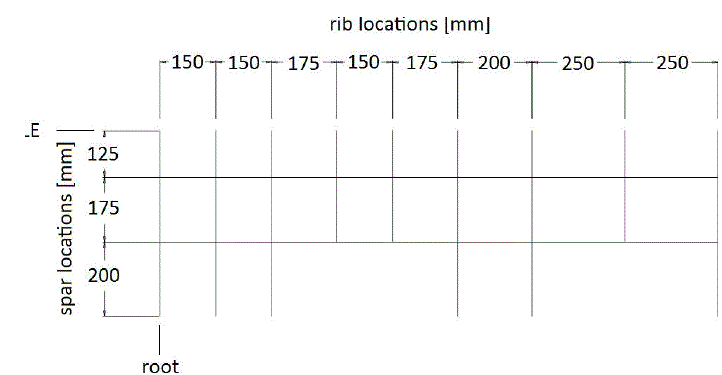 |
| Figure 1: Location of Spar and Ribs from root of wing [mm] |
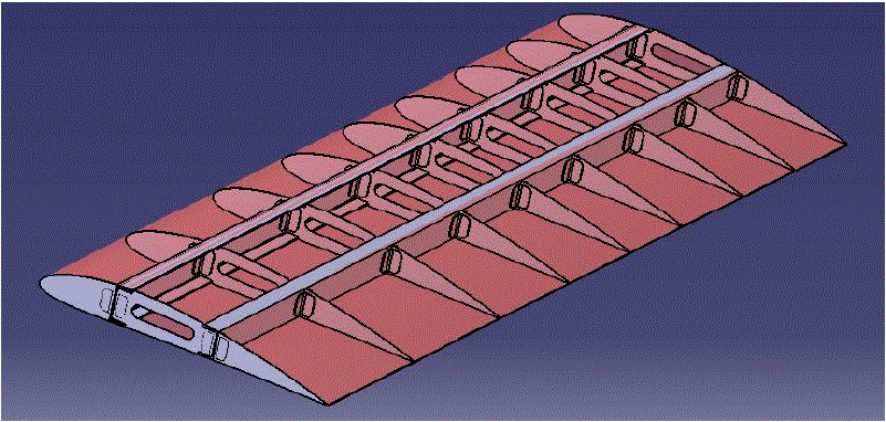 |
| Figure 2: CATIA model of Wing Structure |
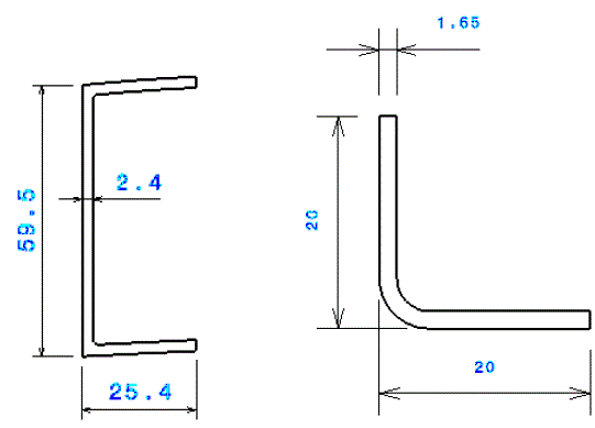 |
| Figure 3: Cross-Section View of Spar and Corner Connector Extrusion |
 |
 |
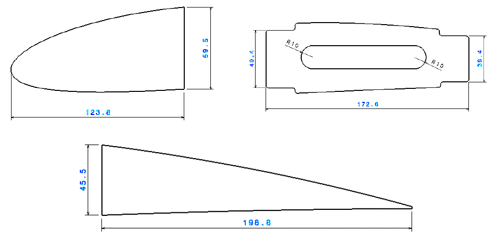
| Figure 4: 2D View of the Ribs |
 |
| Figure 5: FEA model (meshing) of the wing structure |
III. FINITE ELEMENT MODELING STRUCTURAL ANALYSIS OF WING STRUCTURE |
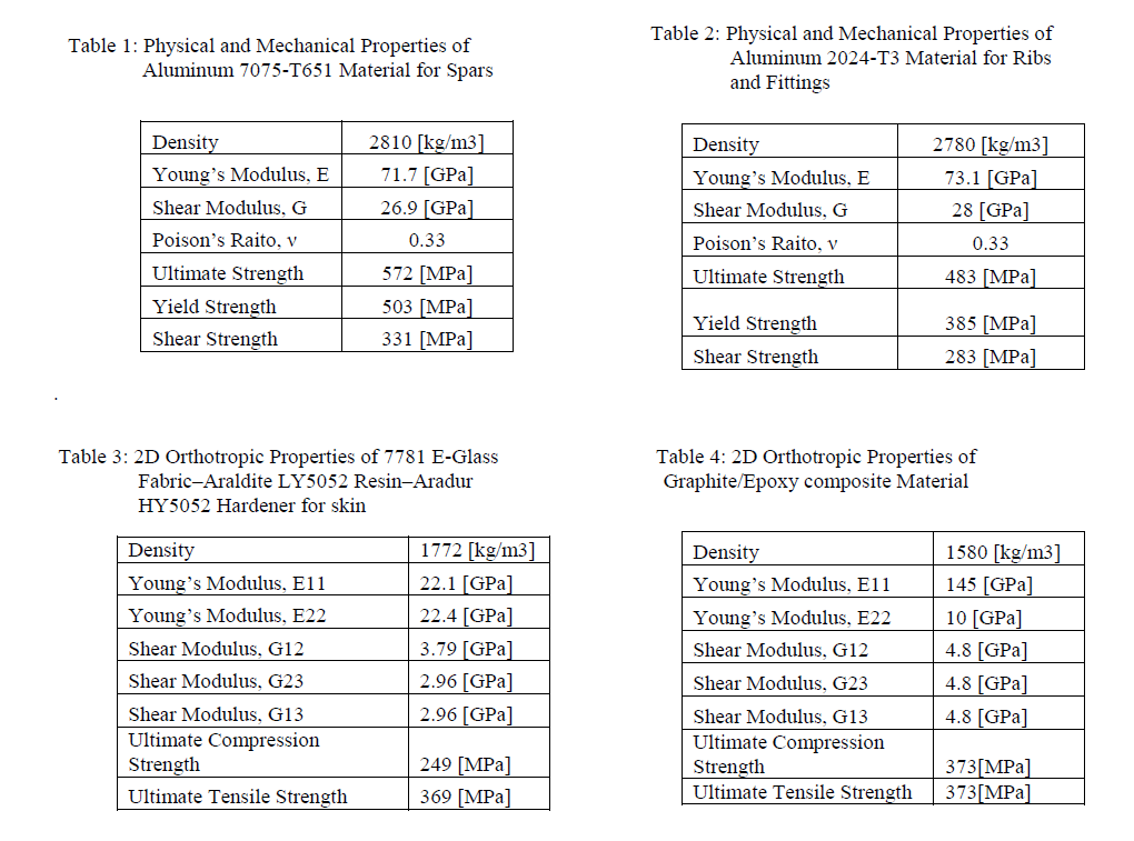
| FE model of the wing structure is as shown in Figure 5. Meshing is carried out by using CQUAD4 shell elements. Verification for the boundary, duplicates is carried out. Normal for each element is assigned. The material properties are assigned to every element in the model. The stress analysis of the wing structure is carried out using the finite element analysis approach. The skin and the ribs were connected by using the equivalence module; and the skin-spar connections were modelled by using RBE2 (Rigid Body Element-2) type multi point constraints. The connections between the members of the inner structure of a wing torque box in practice were generally done by using the fittings and fasteners. The fasteners for the connections were modelled by using RBE2 type multi point constraints. |
Loads and Boundary Conditions: |
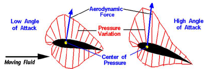
| It was found that, if the aerodynamic force is applied at a location 1/4 chord back from the leading edge on most low speed airfoils, the magnitude of the aerodynamic moment remains nearly constant with angle of attack. |
 |
| The wing structure of an aircraft is connected to the fuselage through keel beam. So the wing structure is act as a cantilever beam connected with fuselage. One end of the wing structure can be fixed and taken as the boundary conditions of the model. This was satisfied by fixing all six degrees of freedom on the nodes corresponding to the fixing point. |
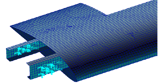 |
| Figure 7: Boundary Conditions Applied on the Wing Structural Analyses |
Wing Structure under Its Own Weight |
| The method in order to model this type of loading was to create an inertial acceleration field which was the equivalent of the gravitational acceleration of 9.81 [m/s2]. Figure 8 shows the inertial field created on the Model. |
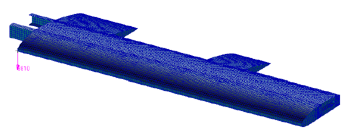 |
| Figure 8: Loading of the Wing under its Own Weight by Using Gravitational Acceleration Field |
| The static analyses were conducted by using the solver 101 module of MSC®/ NASTRAN package program. Figure 9 shows the displacement field of the wing torque box under its own weight. The maximum displacement of 1.19 [mm] occurred at the tip of the wing torque box. Figure 9 also shows the stress distribution on the internal structure and the maximum stress location respectively. The maximum stress value reached at the boundary of the main spar was found as 9.89 [MPa]. Comparing this value with the yield strength of Aluminum 7075-T651, which was given at Table 1 as 503 [MPa], it was concluded that the wing is far safe with a large margin of safety value of 51. |
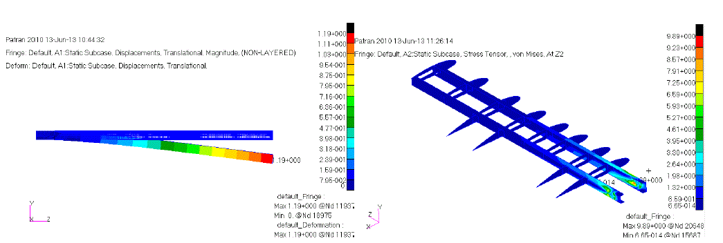 |
| Figure 9: Displacement and Stress field of the wing structure |
| Table 5: Validation with existing Data |
 |
| From Table 5 it is clear that the value achieved for displacement, Maximum Von Mises stress and Margin of safety are very close to the existing data. So the finite element model above developed can be used for the optimisation of the wing structure by changing the orientation of the composite skin plies. |
Wing Structure under Aerodynamic Loading |
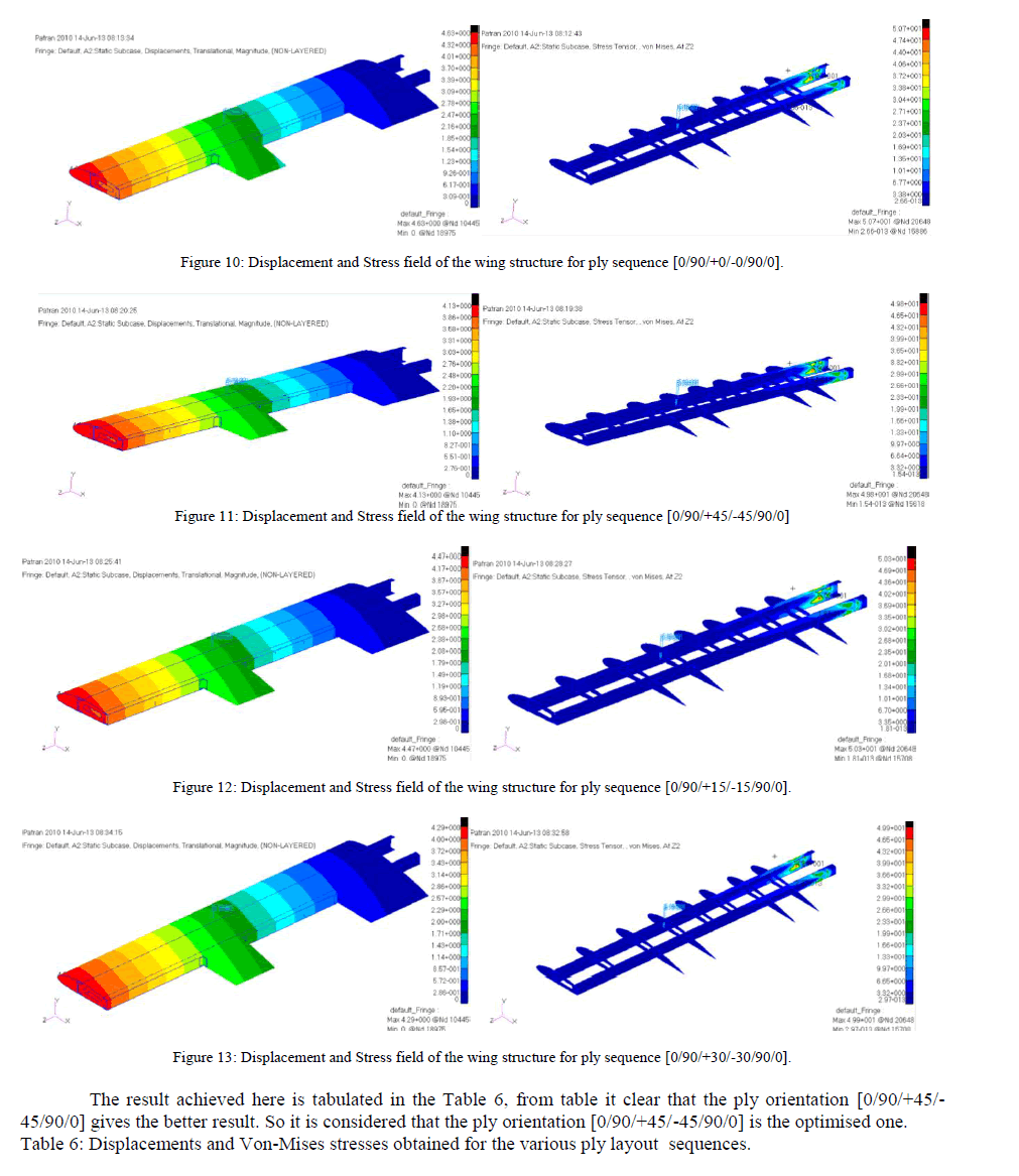
| The aerodynamic loading under the cruise conditions can simply be defined as L = W. The weight of the aircraft under design (unmanned aerial vehicle) is 500N (All-up weight of the aircraft). This load is based on the performance parameters considered for the aircraft. This load will be calculated by the aerodynamic load calculation. When the aircraft is flying at level flight the load factor is equal to „1âÃâ¬ÃŸ. If the aircraft is flying at „1gâÃâ¬ÃŸ condition the load acting on the aircraft will be equivalent to the weight of the structure. Wing is known as lifting component in the aircraft structure. Majority of the lift load will be acting on the wing. The total lift load on the aircraft structure is normally distributed as 80% of the total load on the wings and remaining 20% of the total load on the fuselage. Therefore considering the 80% of lift load on wings, the total load acting on the wings will be equal to 500 X 0.8 = 400N. Therefore the load acting on each wing will be 400/2 = 200N. One end of the wing structure can be fixed and taken as the boundary conditions of the model. A lift load of 200N is applies on center of pressure of the wing for simulating the results. The Ply sequences selected for this study are [0/90/+0/-0/90/0], [0/90/+45/-45/90/0], [0/90/+15/- 15/90/0] and [0/90/+30/-30/90/0] |
 |
VI. CONCLUSION |
| The following conclusions are drawn from the studies conducted. |
| 1. The Von – Mises stress distribution in the case of wing is less towards the wings leading and trailing edges and decreases towards the wing tip. |
| 2. The variation in fiber orientation at the same skin thickness will produce the variation in the Von Mises stress (increase or decrease). |
| 3. Maximum values of Von-Mises stress was observed at the support position of the combined wing. |
| 4. The largest magnitude of displacement was obtained at the free end of the combined wing. |
| 5. The replacement of Aluminium alloy by Gr/Epoxy reduces the total weight of the aircraft wing by 23.7%. |
| 6. The displacement corresponding to the ply sequence [0/90/+45/-45/90/0] is of value 4.63mm and the Von Mises Stress corresponding to this sequence is 49.8N/mm2. By comparing the stress and displacement in Table 6, it is concluded that the ply sequence [0/90/+45/-45/90/0] is seen to have better performance. Thus it is desirable to adopt the ply sequence [0/90/+45/-45/90/0] for composite aircraft wings in comparison with the other ply sequences considered in the present study. |
ACKNOWLEDGMENT |
| I would like to thank Dr. T Nageswara Rao, professor and HOD of mechanical engineering department, The Oxford College of Engineering, Bangalore for his valuable support to develop this project. |
References |
|