ISSN ONLINE(2319-8753)PRINT(2347-6710)
ISSN ONLINE(2319-8753)PRINT(2347-6710)
Anmol Kumar1, M.K. Paswan2
|
| Related article at Pubmed, Scholar Google |
Visit for more related articles at International Journal of Innovative Research in Science, Engineering and Technology
In the present research, an attempt has been made to experimentally investigate the effects of cutting parameters on surface roughness in hard milling of AISI H13 steel with coated carbide tools. Based on face centered cubic method, three-factor (spindle speed, feed rate and depth of cut) and three-level experiments were employed using Commercial statistical software. The surface roughness of machined surface was measured using Surface roughness profilometer (MARSURF PS 1) and then using RSM and analysis of variance (ANOVA) are performed. It is found that the spindle speed and the feed are the two dominant factors affecting the surface roughness. The optimal cutting parameters for minimal surface roughness in the range of this experiment under these experimental conditions are searched. Empirical models for surface roughness are established, a quadratic model best describes the variation of surface roughness.
Keywords |
| Response Surface Methodology, CNC vertical Milling Machine |
INTRODUCTION |
| The advancement of modern technology and a new generation of manufacturing equipment, particularly computer numerical control (CNC) machine, have brought enormous changes to the manufacturing sector. Generally, the handbook or human experience is used to select convenient machine parameters in manufacturing industry. In process planning of conventional milling, selecting reasonable milling parameters is necessary to satisfy requirements involving machining economics, quality and safety. The machining parameters in milling operations consists of cutting speed, depth of cut, feed rate and number of passes. These machining parameters significantly impact on the cost, productivity and quality of machining parts. The effective optimizations of these parameters affect dramatically the cost and production time of machined components as well as the quality of final products. In order to get specified surface roughness, selection of controlling parameters is necessary. There has been a great many research developments in modeling surface roughness and optimization of the controlling parameters to obtain a surface finish of desired level since only proper selection of cutting parameters can produce a better surface finish. But such studies are far from complete since it is very difficult to consider all the parameters that control the surface roughness for a particular manufacturing process. In CNC milling there are several parameters which control the surface quality. The analysis of surface roughness on CNC end milling process is a big challenge for research development. Several factors involved in machining process have to be optimized to obtain a desired surface quality. In this study, three machining parameters are considered viz. spindle speed, feed rate and depth of cut. Computer Numerical Control (CNC) is one in which the functions and motions of a machine tool are controlled by means of a prepared program containing coded alphanumeric data. Hard machining is machining of parts with a hardness of above 45 HRC, although most frequently the process concerns hardness of 58 to 68 HRC. The work piece materials involved include various hardened alloy steels, tool steels, casehardened steels, super alloys, nitrided irons and hard-chrome coated steels, and heat-treated powder metallurgical parts. It is mainly a finishing or semi-finishing process where high dimensional, form, and surface finish accuracy have to be achieved. Since its broader introduction in the mid 1980s in the form of hard turning, hard machining has evolved considerably in various machining operations as milling, boring, broaching, hobbling, and others. Developments of suitable rigid machine tools, super hard cutting-tool materials and special tool (toolholders) designs, and complete setups has made the metal cutting of hardened parts easily accessible for any machine shop. The conventional solution to finishing hardened steel parts has been grinding, but there are a number of clear benefits to the machining of hard parts with a cutting tool. These have justified many existing applications that are growing in number, especially involving turning, boring, and milling. Hard turning was early recognized and pioneered by the automotive industry as a means of improving the manufacturing of transmission components. Gear-wheel bearing surfaces are a typical example of early applications converted from grinding to hard machining using inserts in polycrystalline cubic boron nitride (PCBN). Case-hardened steel components are typical, often having a hardness-depth of just over 1 mm, giving it a wear resistant case and a tough core. Components that make use of this combination of material properties include gears, axles, arbors, camshafts, cardan joints, driving pinions, and link components for transportation and energy products, as well as many applications in general mechanical engineering. Kang et al. [1] carried out a comparative study, evaluating the characteristics of machined steel with a hardness of 28 HRc in a workpiece of planar geometry, varying the angle of inclination to 15, 30, and 45 degrees, using four possible cutting strategies. They used a solid carbide ball nose end mill coated with TiAlN, having a diameter of 10 mm and two cutting edges. They presented a qualitative and quantitative analysis of the surfaces obtained, showing images of the surface texture and graphs of roughness for each condition. The texture obtained for each condition shows the influence of the cutting strategy employed. These authors reported that the strategies employing an ascending cut, with the tool executing the cut from the base of the inclined plane and going up, presented lower values of surface roughness and a more homogeneous texture when compared with the descending strategies. |
| Although the machining of hardened steels presents difficulties during machining, Junz Wang and Zheng [2] showed that it offers advantages in the process and the final machined product, providing improvement in surface quality and dimensional control. A final machining after the thermal treatment, with the material already at the final work hardness, prevents recurrent problems related to the hardness, such as possible workpiece distortion and dimensional variation. One of the more basic and predominant geometric forms in the manufacture of molds and die cavities is the inclined plane. To simulate a finishing condition, geometry of low complexity was adopted, defined as an inclined surface, in one workpiece of definite and reduced dimensions. The main doubt in the machining of this geometry is to know what the best strategy is, defined as the tool trajectory. This includes the workpiece inclination, defined as the angle formed between the tool and a plane normal to the axis of the tool. We consider the ball-nose end mill, which is the type of tool most appropriate for finishing processes on surfaces with complex forms. In the literature, studies of the machining of inclined planes are restricted mainly to evaluating the life of the tool and varying the cutting conditions (feeds and speeds). A smaller number of papers go beyond this and consider the cutting strategies, comparing them with the surface quality obtained. The strategies are defined by the feed and cutting directions, being vertical or horizontal with respect to the plane, and with a direction that can be ascending (upward) or descending (downward). Toh [3] carried out an analysis of the topography of surfaces machined on AISI H13 with hardness 52 HRc. The analysis evaluated different cutting strategies and cutting path orientations, using a planar geometry, inclined at 75°, simulating a finishing process. They used a solid tungsten carbide ball nose end mill, with TiAlN coating, with a diameter of 10 mm and six cutting edges. The objective was to understand the surface texture generated by certain cutting path orientations in a material of difficult machinability. An analysis of the topography resulted in three dimensional graphs of the roughness profile and allowed a determination of the best orientation for obtaining texture of better quality. In conclusion, Toh reported that the strategy involving an ascending vertical cut provided the best results. According to Tabenkin [4], the finishing or texture can be described in terms of the number and direction of the valleys and peaks that compose a surface. The analysis of the surface, in practical terms, can be made in terms of three basic components: roughness, undulation, and form. Generally, the three exist simultaneously, overlapping, although in many situations, it is desirable to examine each condition independently Aman Aggarwal and Hari Singh [5] reviewed various linear and non linear optimization techniques were studied in detail and relative advantages are also discussed and inferred for the non linear optimization methods are the most suited for the optimization of machining processes. The suggestion of the authors is to follow appropriate set of optimization methods based on the problem on hand and also to use a base statistical method to get the initial basic feasible solution and a non linear like genetic algorithm according to the respective problem and solution requirements. |
II DESIGN OF EXPERIMENTS |
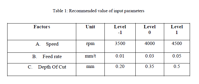
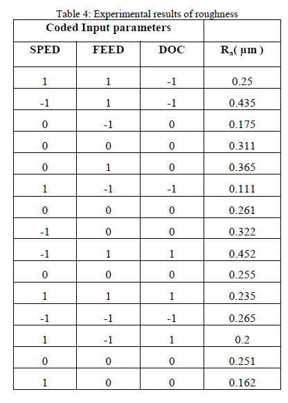
| The design of experimentation has a significant role on the number of experiments needed. Therefore cutting experiments have to be designed in this study a 3 level face centered cubic design were performed to obtain the surface roughness values a total of 20 experiments are conducted at 3 levels for the three input variables speed, feed and depth of cut. Table 1 shows the actual Design data and Table 4 shows the measured Ra with coded parameters. |
 |
III EQUIPMENTS AND MATERIAL |
| The machine used for the milling tests was a „Surya VF30CNC VSâÃâ¬ÃŸ CNC end milling machine having the control system „ FANUC- Oi mate model CâÃâ¬ÃŸ with a vertical milling head. For generating the milled surfaces, CNC part programs for tool paths were created. |
| A. Work Piece Material |
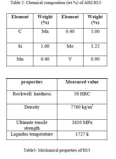
| The work piece material used for present work was AISI H13 alloy steel. The chemical composition of AISI H13 is given in Table-2. The hardness of the material is found around 50 HRC using SAROJ Hardness Testers (Model – RAB- 250) before start of machining. |
 |
| B. Tool Commercially available CVD coated carbide tools have been used for the present investigation. The tools used are flat end mill cutters and the tools are coated with TiAlN coating. Details of the inserts are given bellow: Manufacturer : Mitsubishi material cop. Code : A0MT123608PEER-M Grade : VP15 TF Rake angle (αn) = 11o The insert were fitted to a compatible cutter of diameter 20 mm from the same manufacture i.e. Mitsubishi material cop. Details of the high performance cutter used during the experiments are given bellow: Cutter code : APX3000 R202SA20SA No. of teeth : 2 Nos Maximum ramping angle: 9o C. Surface Profilometer Surface roughness was measured using the “MarSurf PS1” surface profilometer manufactured by Mahr GmbH Gottingen. The arithmetic average roughness values (Ra) was measured by this instrument. The surface finish of the machined H13 steel block was measured after every machining using the profilometer. |
IV MEASUREMENT OF SURFACE ROUGHNESS |
| Surface roughness is measured after each run of experiment. Details of measurement techniques for the measuring surface roughness are given individually in next article. Surface finish values (Ra - arithmetic average) was measured using a stylus profilometer (Mar Surf PS1). Calibration of the instrument automatic of the roughness width cut off based on the roughness values expected. A total of 60 readings were taken to determine the average surface roughness of cut i.e. one reading in the centre of the block and other two readings at a distance of 5 mm from the right side. |
 |
 |
VI RESULT AND DISCUSSION |
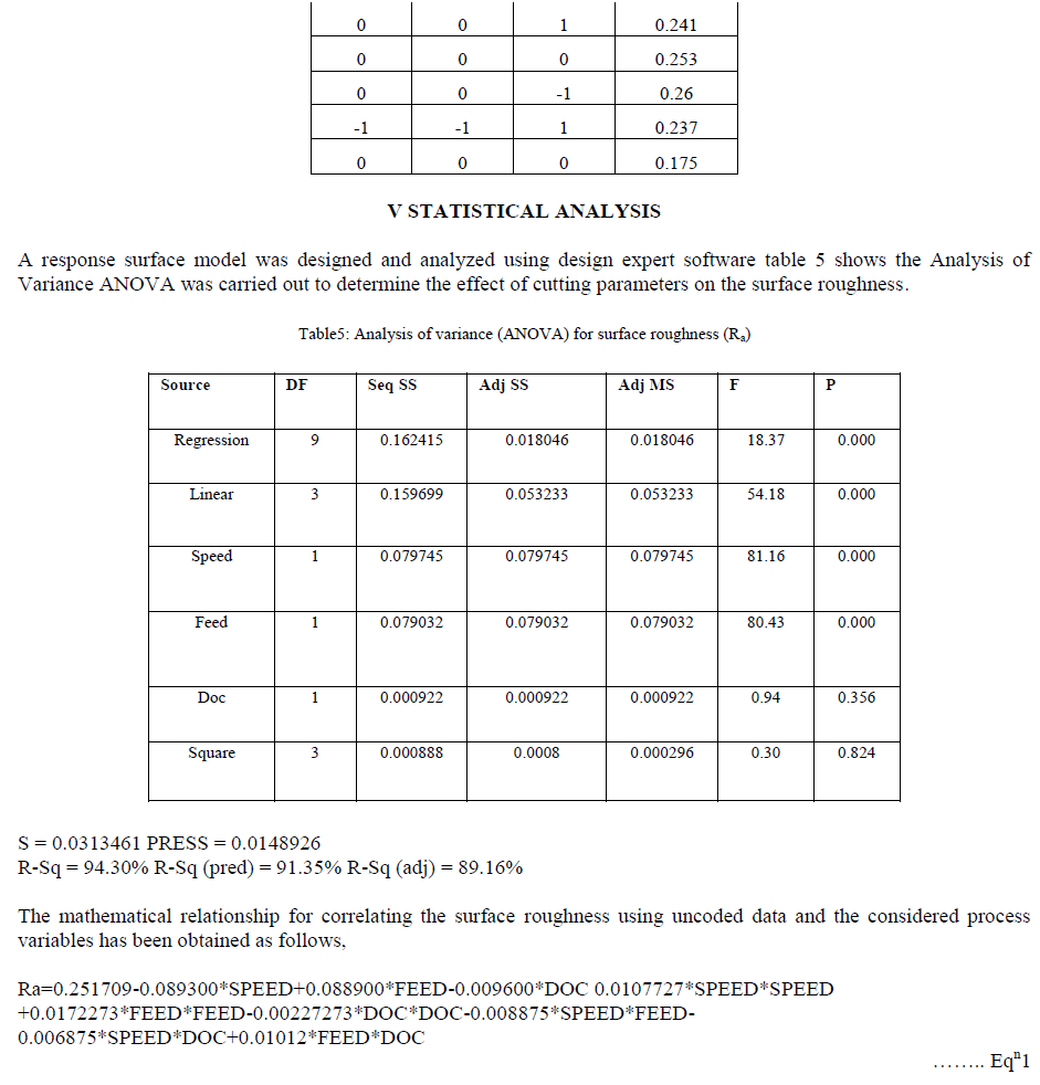
| Using design of experiment, we find that 20 no of experiments will be sufficient for prediction. The surface roughness and tool wear after the machining of AISI H13 for each run with respect to various combinations of input parameters are shown in table 4. |
| A. Effect of Process Parameters on Ra The surface plots physically represent the variation of the roughness parameters with respect to cutting parameters. In each of the surface plots, two cutting parameters are varied simultaneously along X and Y axes while the response parameters are recorded along Z axis. |
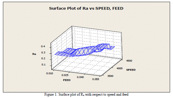 |
| Surface roughness is shown in Z- axis with respect to feed (X-axis) and speed (Y-axis). In the plot, value of surface roughness is increased with increase in feed rate and it is decreased with increased in spindle speed. |
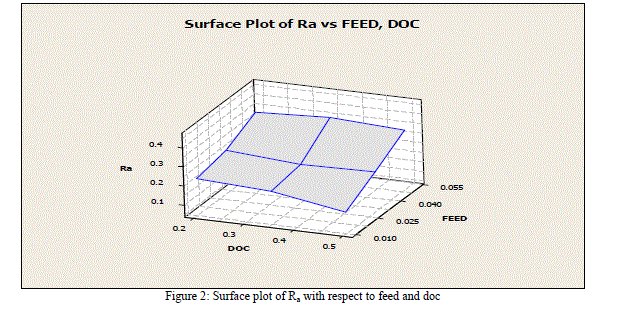 |
| The surface plot graph shows the surface roughness parameters (Ra) in Z-axis corresponding to depth of cut (X-axis) and feed rate (Y-axis). It is see that surface roughness is increased with increase in feed rate but there are slightly changes in surface roughness with increasing the depth of cut as shown in above surface plot. |
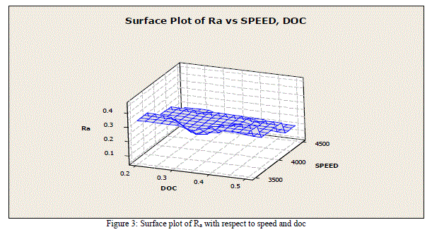 |
| From fig.3 it is clear that at high spindle speed, the value of surface roughness is very small. For the constant spindle speed, if depth of cut is increased, we observe that value of surface roughness is increased. But at higher spindle speed and minimum depth of cut the value of surface roughness is minimum. B. Optimal Process Parameters Here we consider only the surface roughness is the output response for our selected input parameters, for this case we find the optimal cutting parameters and minimum surface roughness after analyzing the process parameters in RSM. We find the optimal solution for speed, feed & depth of cut is shown in table 6. |
 |
References |
|