ISSN ONLINE(2319-8753)PRINT(2347-6710)
ISSN ONLINE(2319-8753)PRINT(2347-6710)
Albert John Varghese1, Rejo Roy2, Prof. S. Thirunavukkarasu3
|
| Related article at Pubmed, Scholar Google |
Visit for more related articles at International Journal of Innovative Research in Science, Engineering and Technology
BLDC motors have the capacity to replace induction motors, but the major setback is the implementation of its drive system which should be efficient as well as low cost and can be implemented easily. Here we try to implement a improved speed control system for a BLDC motor using sensors and easily available controllers which can be utilized for operating under various conditions directly for many applications which will help in the replacement of induction motors with BLDC motor systems. The response of the system has been studied for various speed and load conditions using MATLAB simulation tools.
Keywords |
| BLDC Motor, PID Controller, Intelligent controller, BLDC speed control, Design Optimization |
INTRODUCTION |
| Induction motor is described as the workhorse of the modern day industry having many advantages compared to the other motors, but it has a limited range of speed normally this drawback can be removed as well as the advantages being maintained as it is and added upon by the use of a BLDC motor system. Some of the notable advantages of a BLDC motor are as given below: |
| âÞâ It has long operation life |
| âÞâ It has higher speed range as well as efficiency |
| âÞâ The speed v/s torque characteristics are superior |
| âÞâ The operation is noiseless to some extent |
| âÞâ Compared with other motors the torque-weight ratio is better |
| Conventional DC motors have many attractive properties such as high efficiency and linear torque-speed characteristics. The control of DC motors is also simple and does not require complex hardware. However the main drawback of the DC motor is the need of periodic maintenance. The brushes of the mechanical commutator have other undesirable effects such as sparks, acoustic noise and carbon particles coming from the brushes. |
| Brushless DC BLDC) motors can in many cases replace conventional dc motors. Despite the name, BLDC motors are actually a type of permanent magnet synchronous motors. They are driven by dc voltage but the current commutation is done by solid state switches. The commutation instants are determined by the rotor position and the position of the rotor is detected either by position sensors or by Sensorless techniques. |
| BLDC motors have many advantages over conventional DC motors like: |
| âÞâ Long operating life |
| âÞâ High dynamic response |
| âÞâ High efficiency |
| âÞâ Better speed vs. torque characteristics |
| âÞâ Noiseless operation |
| âÞâ Higher speed range |
| âÞâ Higher torque-weight ratio |
A. Comparison of BLDC motor with other motors |
| In the following section we have made a basic comparison of various machine parameters of a Brushless DC Motor with Brushed DC and Induction Motor and have highlighted the advantages of BLDC over the other types and how it can be widely accepted compared to the other types for the use in industrial as well as for most of the other applications and how a BLDC motor has the capacity to replace all the other types owing to its wide range of advantages and its capability to be applied to almost all applications where a motor is required with just a small drive system. |
|
|
B. Objective |
| Recent research has indicated that the permanent magnet motor drives, which include the Permanent Magnet Synchronous Motor (PMSM) and the Brushless DC Motor (BLDCM), could become serious competitors to the induction motor for servo applications. Motivated by these observations, the objectives of this thesis are: |
| âÞâ Providing theoretical background about the BLDC motor and its controller. |
| âÞâ Designing of Intelligent ANN for adaptive and optimized tuning of PID controller parameters KD , KI , KP. |
| âÞâ Controlling the speed of the BLDC motor using ANN based PID controller. |
| âÞâ Implementing the closed loop speed control of BLDC motor using the software package MATLAB/SIMULINK. |
| âÞâ Comparing the results obtained for the speed control of BLDC motor using conventional PID controller and ANN based PID controller. |
II. BLDC MOTOR DRIVE |
| A brushless DC (BLDC) motor is a rotating electric machine with a classic three-phase stator like that of an induction motor and the rotor has surface-mounted permanent magnets. The polarity reversal is performed by power transistors switching in synchronization with the rotor position. The BLDC motor is driven by rectangular voltage strokes coupled with the given rotor position. The generated stator flux interacts with the rotor flux and defines the torque and thus the speed of the motor. Despite the name, BLDC motors are actually a type of permanent magnet synchronous motors. Brushless DC BLDC) motors can in many cases replace conventional dc motors. |
A. Typical block diagram – brushless dc motor |
| The basic block diagram of brushless DC motor drive system is shown. The brushless DC motor drive system consists of four main parts: |
| ïÃâ÷ DC power supply |
| ïÃâ÷ Power inverter |
| ïÃâ÷ Power electronic Switches |
| ïÃâ÷ Permanent magnet BLDC motor and |
| ïÃâ÷ Controller |
1) DC power supply |
| The fixed DC voltage is derived from either a battery supply, low voltage power supply or from a rectified mains input. The input voltage may be 12V or 24V as used in many automotive applications, 12V-48V for applications such as disc drives or tape drives, or 150V-550V for singlephase or three-phase mains-fed applications such as domestic appliances or industrial servo drives or machine tools. |
 |
2) Inverter |
| The inverter bridge is the main power conversion stage and it is the switching sequence of the power devices which controls the direction, speed and torque delivered by the motor. The power switches can be either bipolar devices or, more commonly, Power MOS devices. Mixed device inverters, for example system using p-n-p Darlingtons as the high side power switches and MOSFETs as the low side switches are also possible. The freewheel diodes in each inverter leg may be internal to the main power switches as in the case of FREDFETs or may be separate discrete devices in the case of standard MOSFETs or IGBTs. |
| The inverter switching speed may be in the range 3 kHz to 20 kHz and above. For many applications operation at ultrasonic switching speeds (>15-20 kHz) is required in order to reduce system noise and vibration, reduce the amplitude of the switching frequency currents and to eliminate switching harmonic pulsations in the motor. Because of the high switching speed capability of Power MOS devices they are often the most suitable device for BLDC motor inverters. |
3) Power electronic switches |
| For the ‘inside out’ BLDC motor it is still necessary to switch the armature current into successive armature coils as the rotor advances. As the coils are now on the stator of the machine the need for a commutator and brush gear assembly has disappeared. The development of high voltage and high current power switches, initially thyristors, bipolar power transistors and Darlingtons, but more recently MOSFETs, FREDFETs, Sensor FETs and IGBTs, has meant that motors of quite large powers can be controlled electronically, giving a feasible BLDC motor drive system. |
4) Motor |
| A two pole BLDC motor with the field magnets mounted on the surface of the rotor and with a conventional stator assembly was shown in Fig.2.1. Machines having higher numbers of poles are often used depending upon the application requirements for motor size, rotor speed and inverter frequency. Alternative motor designs, such as disc motors or interior magnet rotor machines, are also used for some applications. The motor phases are usually connected in a star configuration as shown in Fig |
 |
| Rotor position sensors are required in order to control the switching sequence of the inverter devices. The usual arrangement has three Hall Effect sensors, separated by either 60° or 120°, mounted on the stator surface close to the air gap of the machine. As the rotor advances the switching signals from these Hall Effect latches are decoded into rotor position information in order to determine the inverter firing pattern. |
| In order to minimize torque ripple the EMF induced in each motor phase winding must be constant during all instants in time when that phase is conducting current. Any variation in the motor phase EMFs while it is energized results in a corresponding variation in the torque developed by that phase. The so-called ‘trapezoidal EMF’ motor, shown in Fig.2.7, has a constant induced EMF for 120° and so is a practical motor design which gives optimum performance in a BLDC motor drive system. |
5) Controller |
| The inverter is controlled in order to limit the device currents, and hence control the motor torque, and to set the direction and speed of rotation of the motor. The average output torque is determined by the average current in each phase when energized. As the motor current is equal to the DC link current then the output torque is proportional to the DC input current, as in a conventional DC motor. The motor speed is synchronous with the applied voltage waveforms and so is controlled by setting the frequency of the inverter switching sequence. |
| Rotor position feedback signal are derived from the Hall Effect devices as discussed earlier or from optictransducers with a slotted disc arrangement mounted on the rotor shaft. It is also possible to sense rotor position by monitoring the emfs in the motor phase windings but this is somewhat more complex. In some applications the Hall Effect sensor outputs can be used to provide a signal which is proportional to the motor speed. This signal can be used in a closed loop controller if required. |
B. Basic control techniques of a BLDC motor: |
| The techniques discussed below are some of the motor control options available for the reliable operation and protection of motors. Based on the functions served, motor control can be classified into following categories: |
| âÞâ Speed control |
| âÞâ Torque control |
| Implementation of these control functions requires monitoring of one or more motor parameters and then taking corresponding action to achieve the required functionality. Before getting into the details of these control function implementations, it is important to understand the implementation of logic and hardware required to build up the rotation of the motor or to establish commutation. |
1)Speed control |
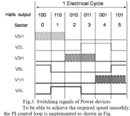
| Following the commutation sequence in a given order helps in ensuring the proper rotation of the motor. Motor speed, then, depends upon the amplitude of the applied voltage. The amplitude of the applied signal is adjusted by using pulse width modulation (PWM). Fig.2.10 shows the switching signals for various power devices. |
| It can be noted from the above diagram that the higher side transistors are driven using PWM. By controlling the duty cycle of the PWM signal, the amplitude of the applied voltage can be controlled, which in turn will control the speed of the motor. |
 |
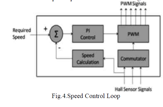 |
| The difference between the required speed and the actual speed is input into the PI controller, which then modulates the duty cycle of the PWM based on the error signal obtained by the difference between the actual speed and required speed. |
2) Torque control |
| Torque control is important in various applications where at a given point of time, the motor needs to provide a specific torque regardless of the change in load and speed at which the motor is running. Torque can be controlled by adjusting the magnetic flux; however flux calculations require complex logic. However, magnetic flux is dependent upon the current flowing through the windings. Thus, by controlling current, torque of a motor can be controlled. |
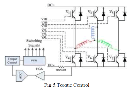 |
| Fig. shows the torque control implementation logic. By maintaining the current flowing through the windings, torque can be controlled. A PI loop similar to that used to control speed can be implemented to smooth the torque response curve with changes in load. |
III. SYSTEM IMPLEMENTATION AND ANN BASED PID INTELLIGENT CONTROL |
| Basically when we use a PID controller for the control of a BLDC motor, we have to manually give the values for parameters like KD, KI, KP , this is considered as a major disadvantage as we cannot keep on changing the values manually for every set speed operation of our BLDC motor. It is at this point we go for the system designed in this project which automatically calculates all the KD, KI, KP values on its own and gives an accurate control of our BLDC motor in all speed ranges. |
A. Block Diagram |
| The diagram below depicts a block diagram of how the optimized speed control for BLDC motor can be implemented |
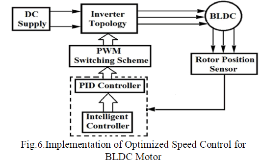 |
| Conventional feedback controllers, such as the PID or the linear quadratic, need accurate mathematical models describing the dynamics of the system under control. This can be a major limiting factor for systems with unknown varying dynamics. Even if a model can be obtained for the system under control, unknown conditions such as saturation, disturbances, parameter drifts, and noise may be impossible to model with acceptable accuracy. For most of the basic electric drives applications, these unknown conditions in addition to the system nonlinearities can be ignored, but it may lead to unacceptable tracking performance. High accuracy is not usually imperative. |
| The conventional PID controllers those are based on linear control theory and are much easier to understand and implement but suffer the disadvantages when the operating points of the process or the plant parameters are changed due to disturbances. For the processes with variable time delays, varying plant parameters, large nonlinearities and considerable process noise, the PID controller does not give optimal performance. Fixed-gain feedback controllers need to be returned to obtain the new optimal settings. For the processes with variable time delays, varying plant parameters, large non-linearities and considerable process noise, the PID controller does not give optimal performance. |
B. Ann based PID intelligent control of BLDC motor |
| BLDCM have been used as variable speed drives in wide array of applications due to their high efficiency silent operation, compact form, reliability, and low maintenance. BLDCM drives were widely employed in industry due to their intrinsic robustness and high torque-toweight ratio. The availability of cheap embedded processing power in recent years paved the way for the widespread use of sensor less control techniques; the removal of speed and position sensors leads to substantial increase of robustness and cost savings. Due to the high torque to volume ratio of BLDCM, it dominates for High Performance Drives (HPD) applications, such as robotics, guided manipulation and dynamic actuation, the precise rotor movement over a period of time must be achieved. Also, the Brushless dc motor, as the name implies, has no brushes. This is an essential requirement for several industrial applications such as airplane actuation, food and chemical industries. This must be achieved even when the system loads, inertia and parameters are varying. To do this, the speed control strategy must be adaptive, robust, accurate, and simple to implement. |
| Some adaptive control techniques, such as the variable structure and the self-tuning, do not need a model for system dynamics. The dynamic model is, rather, developed based on the on-line input/output response of the system under control. These models are usually linear but updated every several sampling intervals for these reasons, properly intelligent methods like Artificial Neural Network (ANN) can be adopted to solve the problems of electric drives as BLDCM control for high performance applications. ANN applications can be divided into four main categories: |
| (i) Modeling and Identification |
| (ii) Optimization and Classification |
| (iii) Process Control |
| (iv) Pattern Recognition. |
| A multi-layer Neural Network architecture is proposed for the speed control of BLDCM that performs two functions. The first is to identify the nonlinear system dynamics at all times. Hence, detailed and elaborate models for the BLDCM are not needed. Furthermore, unknown nonlinear dynamics that are difficult to model such as load disturbances, system noise and parameter variations can be recognized by the trained neural network. |
| The second function of the ANN is to control the motor voltage through tuning of gain parameters of PID controller so that the speed and position are made to follow pre-selected tracks (trajectories) at all times. The control action emulated by the ANN is based on the indirect model reference adaptive control. Artificial Neural Network (ANN) using parallel and distributed processing units can achieve the functions of system mode and control. The ANN has several key features like its robustness, fault tolerant, noise free and capability of generating a nonlinear mapping between the inputs and outputs of an electric drive system without the need for a predetermined model makes it suitable for speed control of BLDC motors under varying load torque. |
C. ANN Based PID Control Of BLDC Motor |
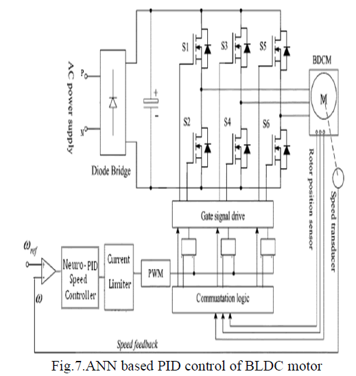
| The overview of the speed control of BLDC motor using an Artificial Neural Network based (ANN) Proportional plus Integral plus Derivative (PID) controller is shown in the Fig. |
 |
| The conventional feedback controllers find wide applications in the process industry. One of the earliest controllers that were used for control was the Proportional- Integral-Derivative (PID) controller. PID controller has proved to be remarkably effective in controlling a wide range of processes. The use of PID controller does not require an exact process model and hence, it is effective in controlling industrial processes whose models are difficult to derive. Moreover, PID controllers are based on linear control theory and are much easier to understand and implement. However, in spite of these advantages of the PID controllers, they possess several disadvantages as well. If the operating points of the process or the plant parameters are changed due to disturbances etc., such fixed-gain feedback controllers need to be returned to obtain the new optimal settings. |
| For the processes with variable time delays, varying plant parameters, large non-linearity and considerable process noise, the PID controller does not give optimal performance. For the control of such highly complex and non-linear systems the PID controllers fail miserably because of their limitations. Recently, work has been started toward the development of Artificial Neural Network (ANN) based PID controllers called Neuro-PID intelligent controllers. A lot of research is going on applications of Neuro-PID in process control and have been successfully implemented. The most widely applied neuro control scheme is the direct inverse model neuro-control approach. In this approach neural network is trained to learn the inverse of the plant either offline or online. Once trained, it can then be configured to control the plant. |
1) Neuro-PID Controller Action |
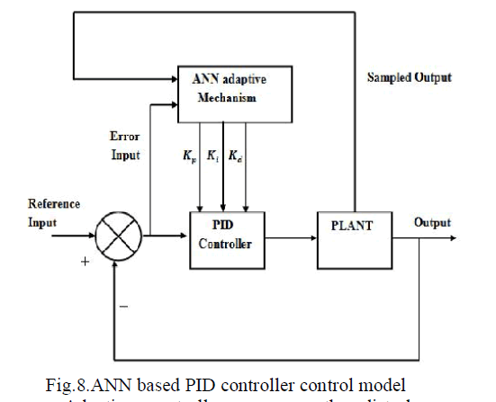 |
| Adaptive controller measures the disturbances from the output and tunes the parameters accordingly so as to minimize the disturbance and improves the performance of the controller. Feed forward adaptive control offers the advantage of fast action without involving any inner closed loops however suffers from the disadvantage of effect of unmeasured disturbances and amount of disturbances. PID gains are tuned by using neural networks. |
| In order to get fast convergence and attain the better solution for a local minimum problem back propagation method is used to tune the PID gains. Neural network can be trained to perform as a controller by learning an inverse model of the plant or as an emulator by indenting the forward model. Among many neural networks learning methods the back propagation algorithm is the most widely used in a wide variety of applications. |
2) ANN Based PID Control Algorithm |
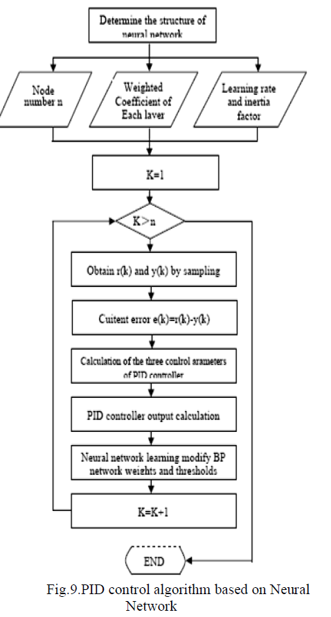
| The specific implementation of PID control algorithm based on BP neural network as shown in Fig.4.9. In control problems, there has been development on neurocontrol for robots control problems. Although various intelligent control methods may be applied to this problem, PID control is a major approach since it is robust to noise and stable for parameter change. Using the backpropagation method, various kinds of neuro-controllers could be trained in such a way that the desired plant output is attained as much as possible. |
| The reason why the PID scheme is adopted here is that the PID controller has been used in the process control system which includes various types of nonlinearities and non-Gaussian noises. The control structure of the selftuning neuro-PID controller is shown in Fig.4.9 where the outputs of the neural network are proportional gain (Kp), integral gain (Ki), and derivative gain (Kd) and the inputs are selected in a suitable way according to the specific problem. |
 |
| There are three typical types of neuro-controllers (a) a series type, (b) a parallel type, and (c) a self-tuning type. The series type neuro-controller constitutes the inverse dynamics of the plant in the part of the neural network. The parallel type neuro-controller is to adjust the control input by using a conventional controller based on the neural network. The self-tuning neuro-controller is to tune the control parameters included in a conventional controller. In our thesis, we consider the self-tuning type of Neuro-PID controller as shown in Fig. |
IV. SIMULATION AND RESULTS |
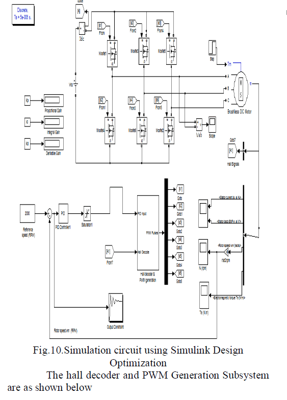
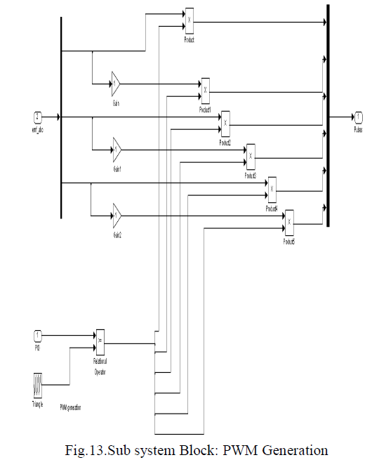
| The closed loop speed control of a BLDC motor using ANN based PID controller as discussed in the previous chapters is simulated using MATLAB 7.9 software package. The circuits are drawn using SimPower System toolbox and the simulated results are also shown in the next chapter. |
A. Simulation Using Simulink System Design Optimization |
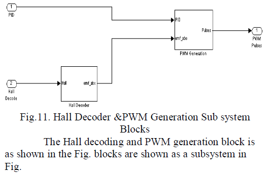
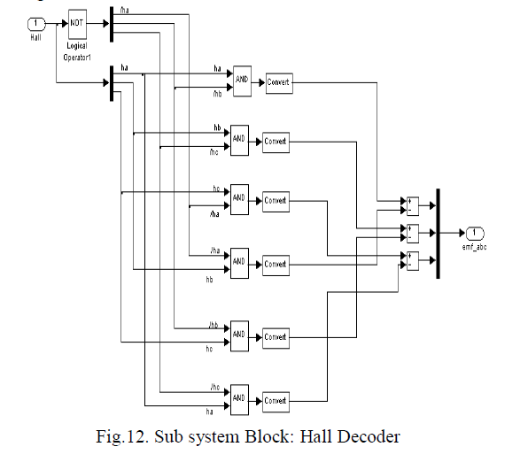
| The speed control of BLDC motor using conventional PID controller and its optimization is implemented using MATLAB/SIMULINK as shown in Fig.. |
 |
 |
 |
 |
B. Simulation Result |
| The figure shown below shows the various simulation results of the Implementation of Optimized Speed Control for BLDC Motor |
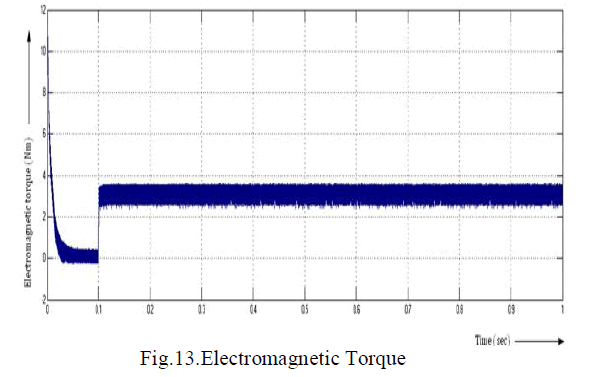
1) Electromagnetic Torque |
| The diagram shown below shows the electromagnetic torque for the simulation of the Implementation of Optimized Speed Control for BLDC Motor |
 |
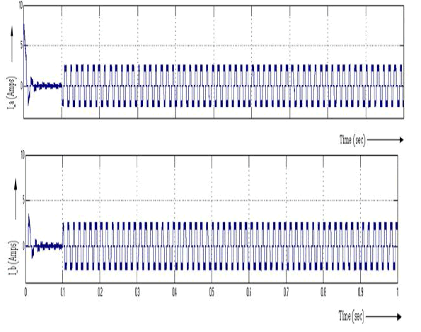
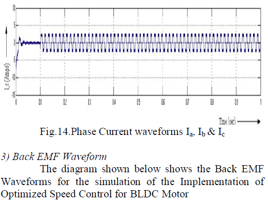
2) Phase Current Waveforms |
| The diagram shown below shows the Phase |
| Current Waveforms for the simulation of the |
| Implementation of Optimized Speed Control for BLDC |
 |
 |
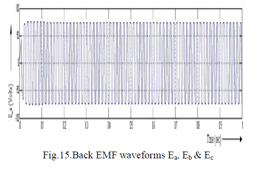 |
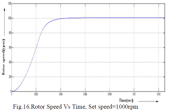
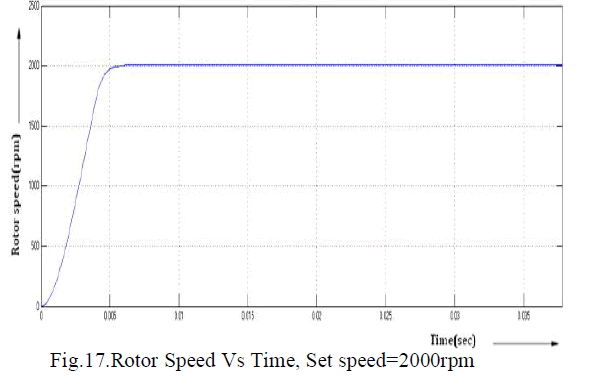
4) Rotor Speed v/s Time Waveform |
| The diagrams given below show the simulation result for the BLDC motor under the proposed scheme |
 |
 |
 |
 |
D. Comparison Of Results |
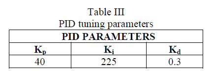
| The performance indices are computed from the results obtained for conventional PID and PID controller based on Simulink Design Optimization and are compared as reported in Table below |
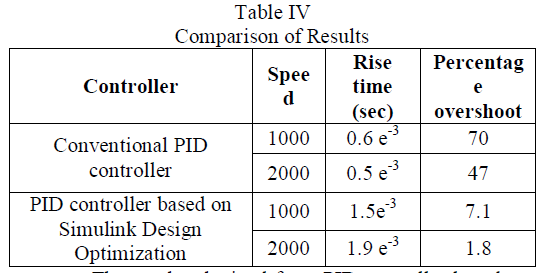 |
| The results obtained from PID controller based on Simulink Design Optimization for speed control of BLDC are analyzed and compared with conventional PID controller. PID controller based on Simulink Design Optimization tool is used to determine the PID controller parameters: Proportional constant, KP, Integral constant, Ki, and Derivative constant, Kd. |
V. CONCLUSION |
| In this project a PID controller model has been developed for the speed control of BLDC motor using MATLAB/SIMULINK. The simulation was done using MATLAB/Simulink System Design Optimization tool. A comparison has been done at various speeds (1000, 2000 rpm) at different load torques ranging from 0-10 N-m of BLDC Motor with PID controller based on and conventional PID controller. The performance indices in terms of rise time and percentage overshoot of the controller are computed and compared. Thus the Simulink System Design Optimization based PID controller improves the response and performance of a conventional Proportionate Integral Derivative (PID) controller in a nonlinear dynamic environment. |
References |
|