ISSN: 2319-9873
ISSN: 2319-9873
Department of Physics, Faculty of Sciences, University of Yaoundé I, P O Box 812, Cameroon.
Received: 09/07/2014; Revised: 21/08/2014; Accepted: 08/09/2014
Visit for more related articles at Research & Reviews: Journal of Engineering and Technology
Being based on generation character of the active centers in chain reactions, combustion process is described with the help of kinetics of the chain interactions, offered by academician N. N. Seminov. Using this mechanism, the paper shows the definition techniques of the basic combustion characteristics: an indicator of combustion and conditional duration of combustion by the display diagram of the diesel engine
Thermal emission, display diagram, duration of combustion.
It is well known that combustion is defined either by kinetics processes or by diffusion. Combustion in all its phases is a set of complex interactive physico-chemical processes. The basis of this complexity is the chemical reaction of a combustible with oxygen.
Combustion as a result of an exothermic chemical reaction is described by simple thermodynamic equations that give the possibility to determine theoretically the air quantity necessary for combustion of given combustible and also the composition and volume of combustible products. Meanwhile those equations do not inform us on the dynamics of combustion process.
The latter can be described if we consider chain interactions proposed by the academician Seminov. This theory considers that the transformation of combustible and air oxygen (combustible in presence of air) is done through various steps where chemical active elements are formed. There is intensive interaction with initial elements and also mutual elements.
Inter-medium chemical active elements are called active centres with one or two free valences. From the character of generation of active centres in chain reactions; it is obvious that the quantity of active centres dn during the time dt is linked with the combustible quantity dm, that is: dm=K dn
Combustion speed of combustible and generation speed of active centres are each other linked by equation:
 (eq1)
(eq1)
Where K – is the coefficient of proportionality
Let us consider the notion of “relative density of active centres”:
 (eq2)
(eq2)
The relative variation of combustible mass is linked with relative density of active centres by the relation;
 (eq3)
(eq3)
On figure 1.a is represented by the variation character of combustion speed of active centres, the combustion of combustible mass – figure 1.b and relative density of active centres – figure 1.c in the combustion chambers of motor.
We can consider the following approximation:
 (eq4)
(eq4)
Where c = proportionality factor
m = power indicator
Obviously, c and m are empirical coefficients.
By replacing the expression eq4 in the eq3,
We have,  (eq5)
(eq5)
After integration from t = 0 to the current time t:

Where M0 – combustible mass at the initial combustion time t=0.
We have,  (eq6)
(eq6)
or
 (eq7)
(eq7)
The value  Considering that
  is the relative fraction of lost combustible at time t,
We note it and therefore
 (eq8)
(eq8)
The formula of eq8 describes the combustion dynamics of combustible in the motor. Meanwhile its practical use is difficult because K and c are unknown.
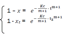
Let us transform the formula for t→α . In that case, x→1, there is complete combustion of combustible. But for real duration process tz, the combustible loss is xz that is always less than unit. Thus the following:’
 (eq9)
(eq9)
Or
 (eq10)
Let us consider that zcorresponds to the value xz = 0.999,
Then ln(1 - xz) = -6.908
Replacing it in eq10, we have
 (eq11)
This was obtained by professor I. I. Bibe for combustible combustion in the motor [1].
The Bibe formula formally represents the combustible combustion kinetics; it is based on active centre generation speed with chain reaction mechanism.
For further use, we change t by the rotation angle of crankshaft. We have  and therefore
 (eq12)
After differentiation; we have the relative speed of combustible combustion:
 (eq13)
Using indicator diagram p= f(φ) obtained by experience, we can have the combustion characteristics. For that purpose we represent the relation x = f(φ). We are interested in the process from initial combustion to the opening of the exhaust valve with M = constant.
For elementary volume of piston displacement, the expression of thermodynamics first law is:
 (eq14)
Where dQ– elementary quantity of heatbrought;
du – variation of specific internal energy of working material;
p – working material pressure;
dv – variation of cylinder working volume;
dQw – elementary quantity of heat from the working material.
Having combustion of cyclic capacity qc of combustible, the heat is Tapez une équation ici.
 (eq15)
Where dx - elementary fraction of the combusted combustible;
If we consider that the working material in the cylinder has properties of ideal gas
PV = NRT and du=CvdT
We have,  (eq16)
Considering that  then,
then,
 (eq17)
Considering  (eq18)
By replacing equations eq17 and eq18 and then solving with respect to dx/dφ
We have,
 (eq19)
Where dx/dφ-combustion speed of combustible;
 – variation speed of relative pressure;
 – variation speed of relative volume;
Thus, heat transmission from working materials;
 (eq20)
Where α(φ) – heat emission coefficient;
F(φ) – instantaneous surface of heat acceptance;
T(φ) – working material temperature;
Tw – temperature of combustion chamber surfaces;
n – rotation speed of crankshaft;
The expressions M and qc are directly measured. The lower heat combustion QN is determined by the quality of combustible.
From the kinematics of crank connecting-rod mechanism, we express 
With construction of indicator diagram by the use of characteristic equation;
We have  , which permits us to determine the real value of isochore specific heat Cv and the adiabatic line factor K.
When having the indicator diagram in the form of curve P = f(φ) or in table form; we can express 
To solve the differential equation eq19, we need initial conditions:
At the start of the observable combustion, the expressions φ0, P0, T0 are known, with x=0 and φ = φ0
From numerical integration of equation eq19 by Runge – Kutta method, we find the dependence of combustible combustion x = f(φ).
Finally, experimentally, we have the curve of combustible combustion as a function of crankshaft rotation angle that permits to express combustion characteristics:
Conditional combustion duration φz and combustion indicator m. To solve the problem we use eq11.
Hence we have  (eq21)
After transformation  (eq22)
or
 (eq23)
Thus,
 (eq24)
Let us consider  (eq25)
Then 
Finally, we have a straight line equation where  is the angular coefficient (fig 2).
 (eq26)
And  (eq27)
Thus, using the experimental indicator diagram P = f(φ) , we determine the conditional combustion duration φz and indicator of combustion characteristic m.
Meanwhile, they depend on the chamber form and on the working regime related to the indicator or on combustion chamber construction or even heat emission will induce the variation of these indicators.
It is important to note that in diesels, the speed of chemical processes is greater than the speed of physical processes that is why the development of combustion reaction is done with respect to lawsof kinetics.
On figure 3, is represented the typical graphic for the speed of diesel combustion.
Contrary to the combustion of homogenous systems in cylinders of carburetors and gas motors, where the curve of heat emission speed is characterized by a simple maximum, in diesels there are two of them. The nature of the first maximum is justified essentially by the kinetic mechanism of combustion. There is combustion of already prepared combustible and air mixture that was formed in combustion chamber. The relative fraction of combustible lost in first phase corresponds to point C on curve 3. The second maximum takes into account the combustion of evaporated combustion of evaporated combustible drops in combustion chambers where the speed of kinetics reactions is limited by the speed of reactive materials diffusion. In this phase, the process is characterized by the fact that the mixture has diffusive (and turbulent) nature. The relative fraction of combustible lost in this phase is the value 1-Xc (see fig. 3). The resultant curve of lost combustible speed can be expressed as sum of two curves 1 and 2 (Figs.3).

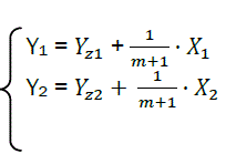
Each phase of combustion in X – Y coordinates corresponds to its own straight line (Fig. 4).
We represent parameters related to the first part with the index 1, and the second part with index 2.
 (eq28)
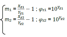
Finally, it is possible to calculate the combustion characteristics:
 (eq29)
The intersection of 1 and 2 is the point C – the limit of part I and part II combustion phases.
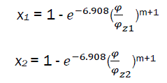
if  (eq30)
By solving simultaneously eq30 with φc, we have
 (eq31)
It is possible using experimental data to describe the process of heat emission with combustion of heterogeneous mixtures in the diesel.