ISSN ONLINE(2319-8753)PRINT(2347-6710)
ISSN ONLINE(2319-8753)PRINT(2347-6710)
P.Satyanarayana1, Subramanyam Pavuluri2, Dr. A.Siva Kumar3
|
| Related article at Pubmed, Scholar Google |
Visit for more related articles at International Journal of Innovative Research in Science, Engineering and Technology
The present paper deals with a issue of steam turbine blade efficiency. Based on the theory of vibration of mechanical structures, the dynamic behavior of a turbine blade, blades or the blades disc assembly can be predicted. The evaluation of a blade design is made by combining the dynamic behavior with the nature of the fluctuating forces. The basic design consideration is to avoid or to minimize the dynamic stresses produced by the fluctuating forces. Since these forces are periodic one has to consider a several number of these harmonics coincides with any of the natural frequencies of the blades. Generally a Campbell diagram is drawn to ascertain this. In this connection an attempt is made on estimate the dynamic behavior of a blade and the stresses occurring in the blade of steam turbine in the last stage due to centrifugal force. The stresses occurring at the disc groove where it gets in contact with root are analysis natural frequencies and mode shapes were obtained and Campbell diagram were plotted and verified with the experimental data. Since the blade is long and twisted it needs a lot of input to accurately define the complete geometry. Blade geometry is defined by giving different profile data at different heights. The results and conclusions are presented for a study concerning the durability problems experienced with steam turbine blades.
Keywords |
| Steam Turbine, Turbine Blades, Strength, Efficiency, Life. |
INTRODUCTION |
| Moving blades in a turbine are loaded by centrifugal forces and forces exerted by the working fluid (Steam or gas). Depending on the design of blades and the operating conditions, centrifugal forces may develop tensile, compressive or tensional stresses in moving blades. The forces exerted by the working fluid may bend or twist a blade, through torsional stresses are usually very low compared with bending ones. In this survey emphasis is placed on papers dealing with general structural analysis of blade by analytical modeling, blade excitation and its response, fatigue life estimation and experimental evaluation of turbine blades. |
Analytical modeling - General: |
| There has been continuing improvement in the analytical modeling for the determination of natural frequencies of the system comprising of a set of blades mounted on the bladed disk. The early attempts to model the blade as a beam element have gradually led to a more detailed finite element representation. This finite element representation of real blade profile becomes necessary especially when plate or shell type of vibratory modes is induced. Subramanyam Pavuluri et.al [1] The Experimental investigation on design of high pressure steam turbine blade addresses the issue of steam turbine efficiency. A specific focus on aerofoil profile for high pressure turbine blade, and it evaluates the effectiveness of certain Chromium and Nickel in resisting creep and fracture in turbine blades. The capable of thermal and chemical conditions in blade substrate from to prevent the corrosion when exposed to wet steam. The efficiency of the steam turbine is a key factor in both the environmental and economical impact of any coal -fired power station. To increasing the efficiency of a typical 500MW turbine by 1% reduces emissions of CO2 from the turbine station, with corresponding reductions in NOx and SOx. In this connection an attempt is made on steam turbine blade performance is important criterion for retrofit coal fired power plant. Based on the research presented modifications to high pressure steam turbine blades can be made to increase turbine efficiency of the turbine. The results and conclusions are presented for a study concerning the durability problems experienced with steam turbine blades. Rao J.S et.al [2] made a two - dimensional analysis of free vibrations in the tangential direction. The first step is to develop the potential and kinetic energies for the tangential motion of the blades and shrouds. Second, Hamilton's principle is applied to derive the differential equation of motion and the boundary conditions. Then these equations are solved to determine natural frequencies. Leissa.A.W et.al [3] made a comprehensive study of the numerous previous investigations on the free vibration of twisted cantilever plates of rectangular platform which are results of a joint industry, government and university effort. Theoretically results received from different FEM programs utilizing shell theory and beam theory were compared with two independent sets of data obtained from experiments. Reasonable agreement among the theoretical results was found but it was recommended that further improvement in analysis method is necessary for increased reliability. Park et.al [8] deal with the failures of turbine blades. Failures of turbine blades are identified as the leading causes of unplanned outages of steam turbine. Accidents of low - pressure turbine blade occupied more than 70% in turbine components. Therefore for preventing failures they had implemented the case study. This procedure is used to avoid costly, unplanned outage. in this they are trying to find factors of failures in LP turbine blade & to make three steps to approach the solution of blade failures. First step is to measure natural frequency in mockup test & to compare it with nozzle passing frequency. Second step is to use FEM & to calculate the natural frequencies of 7 blades & 10 blades per group in blade code. Third step is to find natural frequencies of grouped blade off the nozzle passing frequency. |
Blade excitation and response: |
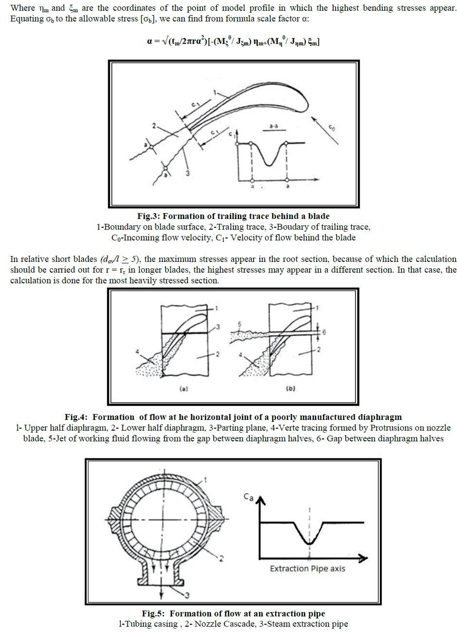
| The major sour of blade excitation arises out of the interaction between the moving blade rows and the stationary blade row. A logical approach towards the design of turbo machine blade is to study the nature of these excitation forces and analyze the dynamic stresses. Many researchers have worked to developed the basic theories of isolated airfoil and have studied the flow interference in a turbo machinery stage. Rao.J.S et.al [2] derived the equations of motion of blade on a disk rotating with angular velocity. The acceleration of the disk is taken as constant. They have obtained the forced vibration response of turbine blades during operations such as step-up and down, involving variation in angular velocity with time. They have shown that the acceleration values have significant influence on the blade response. the governing equation of motion of a cantilever blade on a rotating disk with variable angular velocity have been derived. Corolis forces are included in the derivation. The equation is a non-linear integral partial differential equation. A solution of this equation is obtained by Ritz averaging principle. Rao.J.S et.al [10] estimated the life of turbine blades. The practice of during blades from possible resonance near operation conditions is no more an acceptable criterion in the design of modern steam and gas turbines. With the advent of high-capacity, low-weight and high-speed design of these machines it is becoming essential to estimate the blade life at the design stage itself. The free vibration analysis to determine natural frequencies and mode shapes and the critical speeds on the Campbell diagram are established. The problems of excitation force, damping values near a resonant condition are addressed along with some aspects of cumulative fatigue damage, for determining life of a given blade. |
Fatigue life estimation: |
| Vibration induced fatigue is very common for turbo machine blading and this aspect is undergoing continues investigation. Fatigue crack normally initiates from the zone f high stress, having metallurgical or structural discontinuity and this may grow and lead to the failure due to operating conditions. Vyas.N.S et.al [15] developed the fatigue life estimation procedure for a turbine blade under transient loads. they presented a technique for fatigue damage assessment during variable-speed operation. Transient resonant stresses for a blade with non-linear damping have been determined using a numerical procedure. A fatigue damage procedure is described. The fatigue failure surface is generated on the S-mean stress axes and miner's rule is employed to estimate the blade stiffness and other operating parameters. |
| Murari P Singh et.al [16] highlighted the fatigue damage of steam turbine blade caused by frequency shift due to solid build up. They discussed how due to the solid built up at the blade root shifted the natural frequency into interference, and changed the response characteristic of the bladed disk assembly. Walls.D.P et.al [17] predicted the life of turbine engine blades under vibratory high cycle fatigue. A novel fracture mechanics approach has been used to predict crack propagation lives in gas turbine engine blades subjected to vibratory high cycle fatigue (HCF). The vibratory loading included both a resonant mode and a non-resonant mode, with one blade subjected to only the non resonant mode and another blade to both modes. A life prediction algorithm was utilized to predict HCF propagation for each case. The stress intensity solution was calibrated for crack aspect ratios measured directly from the fracture surfaces. The model demonstrates the ability to correlate predicted missions to failure with values deduced from fractographic analysis. This analysis helps to validate the use of fracture mechanics approaches for assessing damage tolerance in gas turbine engine components subjected to combined steady and vibratory stresses. |
Experimental evolution: |
| Rotating blades have been recognized as one major cause of failure in many turbine and jet engines. They are, usually rotating at high speeds, interacting with the erosive environment, have complicated shapes, and undergo server dynamic and thermal loadings. These operating conditions expose blades to many vibration excitation mechanisms and the same time make the vibration measurement process of blades a very complicated task. Experiments are done to evaluate the frequencies of blades. Rao.J.S et.al [13] has done experiment to determine overall damping in a rotating turbine disc-blade system. A test spin rig has been designed and fabricated. Transient excitation of rotating blades is caused by suddenly shutting off the excitation to the rotating blades. Frequency analysis of the transient blade response gives the information about the modal damping with the speed of rotation and strain amplitude is obtained. Al-Bedoor.B.R et.al [14] measured the blade vibrations in turbo-machinery. A blade vibration has been recognized as failure of turbo machinery, which has developed enormous efforts towards developing reliable techniques. They can be classified into broad categories namely the direct approach, such as using strain gauges bonded at the blade, and optical/laser methods to monitor the blade motion directly at one or more points on the blade span and the indirect approach, by extracting vibration, casing/bearing cap vibration, pressure fluctuations, performance monitoring of torsional vibration. By using these techniques he measured the vibrations in turbo machinery. |
Problem Definition: |
| Model analysis is conducted in static condition and by rotating the blade at various RPM. The free-standing blade is constrained for all degrees of freedom at the base of the blade where it is attached to the root. in this analysis the prestressed effect f the blade is also considered. Due to the self-weight when the blade rotates at different speeds its frequencies are obtained for these four modes and Campbell diagram is drawn. The single blade with its fire-tree root and disk groove sector is considered for the stress analysis to obtain the stress distribution in the blade, root and also disk groove. Parametric macro is developed for modeling and stress analysis of the steam turbine blade. From model analysis different frequencies are obtained for different speeds which happen due to centrifugal stiffing and blade untwisting. |
II. STATIC STRENGTH OF MOVING BLADES |
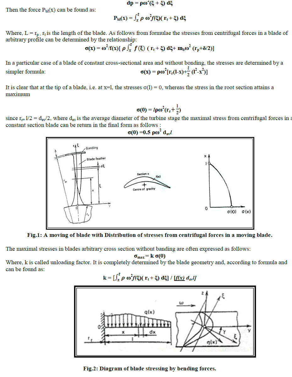
| Tension of moving blades by centrifugal forces. Let a moving blade of an arbitrary profile have a banding of mass mb at the periphery (tip). The root section of the blade has the radius rr and the peripheral section, radius rp. The area of the blade profile in a section x may be denoted as f(x). Let the x axis be chosen so as to pass through the axis of rotation of the latter. It is assumed that the centre's of gravity of all blade section lie on the axis x.The tensile stress σ(x) in section x can be found by the formulae. |
 |
 |
| The factor k shows how much the stresses in the root section of a blade of an arbitrary profile differ from those in the root section of a constant-section blade. As a rule, turbine blades are designed from the strength consideration so that unloading factor is less than unity. To achieve this, the cross-sectional area f(x) of a blade should be made decreasing from the root to tip. If the cross-section are varies linearly from the root to tip, then |
 |
 |
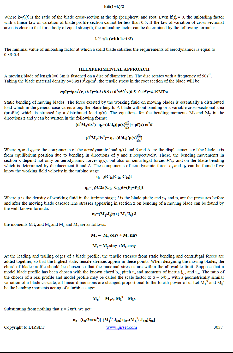
| If moving blades are tied by a banding or wire, the bending moment acting on the blade feather decrease, since part of the bending force is absorbed by the banding or wire. In the limiting case (with an absolutely stiff banding), the bending stresses in the blade feather can be reduced roughly by one third. If the blade axis is straight and arranged radials, centrifugal forces will tend to returned into the initial equilibrium position, i.e. they will counteract the bending forces. Calculations show that the reduction of bending stresses in moving blades of the first and intermediate turbine stages due to centrifugal forces does not exceed 10% and can be neglected. For long blades, the effect of centrifugal forces on static bending is substantial and is taken into account in calculations. |
IV. CONCLUSIONS |
| The study presents the technique and methodology for studying the vibration behavior of turbine blade. The study highlights the fact that although the major advances have been made in the blade vibration design technology, failures still take place, there by emphasizing that blade behavior is complex. Finite element results for free standing blades give a complete picture of structural characteristics, which can be utilized for the improvement in the design and optimization of the operating conditions. The results are correlated with the experimental results and varying the profile to get the optimum results. The final blade profiles obtained after complete analysis was free resonance in the operating region. The profile point coordinates are generated and send to manufacture for manufacturing the blade. The above results can give more accurate values of dynamic stress levels, if the magnitude of dynamic force experienced by the blade is exactly known. The blade is subjected to such force due to flow excitation and flow disturbances under various operating conditions. The result obtained from the analytical work matches quite closely with experimental results thus showing the accuracy of the model and adequacy of boundary conditions. An attempt is made to model the blade for wide frequency operation. Considerable work in this area is still required and should be attempted to completely analyze the blade behavior. |
References |
|